


The Cast Iron Jigsaw
Restoring the Camellia House at Wollaton Hall
Stuart Armitage
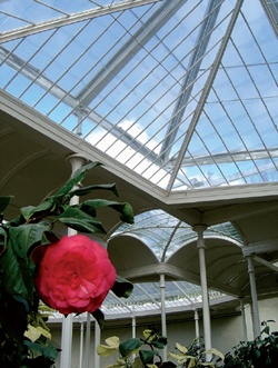 |
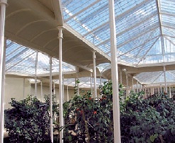
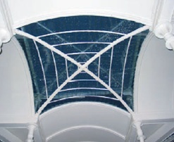
| Figure 1: Interior of the restored Camellia House |
Rather forlorn and dogged by vandalism, by 2004 the Camellia House at Wollaton Hall, Nottinghamshire was closed to the public. The once grand glasshouse had sadly been fenced off, both to protect the public from falling debris and glass, and to prevent further damage to the structure.The glasshouse was built in 1823 for the Willoughby family, owners of Wollaton Hall, and was designed especially to house the stunning camellia plants they collected.
In plan, the building is laid out with four quadrangles, each of which is covered by a glazed pitched roof (see Figure 3). These roofs drain into a gutter around their perimeter. The walkways which separate and surround each quadrangle are covered by barrel roofs comprised of wrought iron panels which span between the gutter positions. To convey the water from the roofs into an underground rainwater system, the gutters drain down through the structural columns which support them (see Figure 4). In addition to using the columns as downpipes, the builders had quite boldly selected glazing bars with a very small section, no doubt at the insistence of their clients, to give maximum light within the Camellia House.
Two of the four perimeter walls of this building are fully glazed with iron glazing bars and a mixture of timber and iron doors. The other two walls are constructed of brick faced with render, and contain a number of recesses for statues and benches. To the rear, where the wall forms a retaining wall, there is a boiler house, and at the bottom of a floor-well the remains of the boiler were found. This, we believe, would have heated rainwater to provide a hot and humid atmosphere throughout the building as, at that time, it was not realised that camellias are in fact quite hardy. A large cistern was also uncovered during the works. Hot air was circulated through an ingenious arrangement of pipes, underground gullies and vents, as well as through brick vaults beneath the beds themselves. This must have required a fairly sophisticated control system, allowing the climate of the glasshouse to be carefully managed.
However, as with many cast iron structures, the ingenuity of its design was also its Achilles’ Heel. In particular, incorporating the rainwater drainage system into the structural components of the Camellia House was clever, but it also seriously compromised the structure’s longevity.
Although the poor condition of the building had been recognised before the restoration work began, it soon became apparent that the defects were much more extensive than could have been foreseen at the outset. This was mainly due to the enormous build up of paints and fillers which had been applied on an ad hoc basis over the years.
The project team included Purcell Miller Tritton architects, who led the project, engineers from The Morton Partnership, who advised on the repairs, and Dorothea Restorations, the contractor carrying out the works. The project was part of a larger one which covered the whole Wollaton Estate, and was run in parallel with extensive repairs to the main hall under the same project team.
The overall cost of the restoration was approximately £1.1million, and the work lasted just under two years. Thankfully, all of the repair works were carried out with the camellias in situ and without them suffering any damage. Indeed by the time of the re-opening in 2007, the camellias were already flowering.
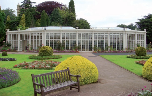 |
| Figure 2: The restored facade |
DISMANTLING, RECORDING AND INVESTIGATION
The process of renovation involved dismantling the structure to allow proper fabric assessment, repairs and sealing between components to prevent water ingress. This approach also allowed the rainwater system to be properly overhauled and repaired.
With approximately 900 components of cast iron, wrought iron and glazing elements, from the very start it was essential that an appropriate logging and identification system be established. A database was set up so that each of the components could be individually tagged with an identity number. This process allowed all components to be tracked continuously, from the time of removal from site right up to the time they were returned and reinstated in the building.
 |
|
| Figure 3: Roofscape showing glazed pitched roofs with barrel roof in the foreground prior to restoration |
This, however, was only one part of the process to ensure that the building was reconstructed to the exact same configuration as before. Over a period of 180 years considerable settlement had occurred to the building, and general allowances had to be made for these variations and for irregularities in the original castings which were found to be far from precise. This required meticulous surveying and setting-out. A full dimensional survey of the structure was therefore undertaken, both in the horizontal and vertical planes, so that at key node points it would be possible to set the building out exactly as it was found. This meant that some gaps would remain between components, but generally these discrepancies would be distributed over the structure rather than ending up with a shortfall at one position or another or ending up with components that simply could not be drawn together.
The system of data tagging also allowed each component to be identified in terms of the proposed repair types, and generally operated as a useful tool in managing the process.
THE DEFECTS
Various masonry repairs to the rear wall, which incorporated hidden lead downpipes, as well as repairs to the boiler room and adjacent stonework were necessary. The repairs to the ironwork, however, were particularly challenging and required a large amount of careful decision-making to ensure that the most appropriate type of repair was used in each case. The vast number of components meant that the decision-making process for repairs needed to be clear, confident and rapid.
Once the components had been returned to the workshop of Dorothea Restorations at Whaley Bridge in Derbyshire, each was gathered together according to type and then gritblasted to reveal the true condition of the fabric beneath the layers of rust and paint. Not only were extensive additional defects discovered, but also numerous historic repairs were found, some of which were still sound (see Figure 5).
Generally, the components could be categorised as being either small items of decoration or related to the glazing elements, or large elements relating to the main facades and structure. The large elements included 61 columns and many cast facade plates, some of which were in the order of five metres long by one metre deep.
It was clear that the idea of incorporating rainwater drainage into the structure had been fundamental to its design. For example, the ribs which act as rafters between the glazed panels and which also support the wrought iron coverings to the walkways, all incorporated a central rill to carry water from the adjacent panels down into the gutters. The gutters themselves are the spanning element between the column positions and are carefully moulded at the head of the columns so that the water collected would then discharge down through the column to the base and the underground system.
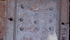
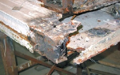
Predictably, much of the decay was identified around the key fixing positions and the positions where members were seated together (see Figure 6). Often it was necessary to make the repairs flush with the original surface in order for the component to fit, and indeed this type of repair posed certain difficulties in itself. The key defect positions were at the bottom of the ribs and on the columns themselves. There were also quite extensive fractures in the cast gutters, and general movement of the building had caused fractures within the large plates associated with the facade.
 |
 |
| Figure 5: Earlier plate repair | |
 |
|
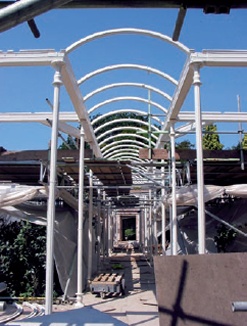
| Figure 4: Internal columns and gutter beams. The hollow columns also serve as downpipes | Figure 6: Typical corrosion at joint of cast iron members |
 |
 |
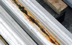
| Figure 8: Column ends showing off-centre cores and lining materials from earlier repairs | |
| Figure 7: Fractured column |
Damage to the columns was primarily the result of corrosion and frost action which had caused fractures to occur, often with splits from top to bottom (see Figure 7). Several factors were responsible. Firstly, the rainwater conduits within were only 38mm in diameter and were easily blocked by falling debris. Secondly, in many cases the core appears to have floated when they were first cast, resulting in a thinner wall section on one side of the column. This was made worse by the deeply recessed moulding to the external face of the column, which in some cases meant that there was only 6mm or so of material between the recess on the outer face of the column and the edge of its hollow core. In a number of cases, historic attempts to line the columns with plastic or lead pipes had in fact made the situation worse, either because rainwater from the top found its way between the sleeve and the iron, or because condensation had accumulated between the two materials, causing further decay (see Figure 8).
Within the smaller components the quality of the original castings was reasonable. Due to their size, the distortions in them were proportionally fairly small. However, extensive areas of the larger components were pitted with holes and in fairly poor condition and many suffered from a significant degree of warp across their full surface area.
Problems like these often go unrecognised until the really detailed stage of a project when every single component is studied, and this was quite a painstaking and lengthy process. It was, however, significant that by working closely with the contractors in their workshop, this process was made very much easier and a principle was established for dealing with each type of situation which could then be repeated as necessary.
A further problem was presented by the high iron content of the castings: within hours of grit-blasting a component the orange discolouration of rust was beginning to develop. This meant that, before the final painting process, each component had to be lightly blasted once again.
REPAIRING THE IRONWORK
In terms of the rationale for the repairs, the
key to this type of structure relates to its
overall appearance. It was realised very early
on that, on a local scale, the repairs needed to
be functional and robust due to the structural
role of many of the components. However,
the beauty of the structure is primarily
appreciated when the building is viewed in
its entirety, rather than in detail, so there was
little requirement for invisible repairs. Indeed
it is doubtful whether repairs could have been
achieved which would have been both truly
effective and invisible.
In terms of the repairs, there was a proportion of re-casting required, and this particularly applied to the columns which formed the downpipes. As several of the columns needed to be cast, it was most efficient to make a new timber mould based on one of the original columns and use this for the recasts. To solve the problem of the floating core, small sacrificial pins were introduced between the core mould and the outer mould to hold the core in place and ensure a consistent wall thickness around it. The pins then melted into the casting.
Other repairs included limited welding and stitch repairs between non-structural elements, particularly to the large facade plates, and some bolted structural repairs, particularly related to the bottom of the roofing ribs. For aesthetic reasons, the number of large plated repairs that would be visible externally was kept to a minimum.
Where the cast ribs were found to be rotten at the lower end, the metal was cut back to sound material and new ends were cast and then secured by dowels to the original. This process was carried out by drilling the new casting then tapping this hole so that a threaded pin could be used to secure the new and existing sections together. The dowel was resin fixed into the existing casting, and the joint notched and welded.
 |
|
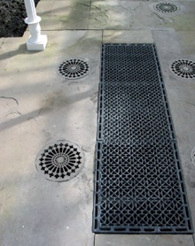
| Figure 9: Floor vents of heating and humidification system |
The final element was the repair of the floor beams. The floor system incorporated the drains and the humidifiers. It consisted of deep trenches running beneath all of the paths to allow water collected from the roof to be heated by circulatory pipes. Bronze grilles in the floor above then emitted warm, moist air back into the Camellia House (see Figure 9). The slabs over the top of these deep drainage gullies, which were up to 1.5m wide, were supported on T-section cast iron joists, with the vertical web members becoming deeper towards the centre, and the joists terminated in a heavy block at each end. There were complicated joist intersections beneath crossing paths including cast dovetail joints.
Removal of the floor slab was possible only after the building had been dismantled since most of the perimeter paving was inaccessible beneath the cast walls of the Camellia House. Once lifted it was obvious that many of the joists were rotten. The rot particularly occurred at the position where the beam spanned over the bearing position and at the face of the drainage channel. These members clearly had to be replaced, and either stainless steel angles or new cast iron joists were used. There were other members which appeared to be sound, but on close inspection minor fractures could be seen. Although small, these were potentially sufficient for the members to fail.
At that stage in the works, we talked in some depth about options for investigations, even fleetingly considering the idea of x-raying the members in order to reveal minor fractures. However, it was decided that the most pragmatic approach was to test the beams on site. For this a rather rudimentary approach was taken; each of the beams was simply propped on bricks at either end so that they spanned freely. Then, in turn, each of the beams was stood on by the engineer or a contractor. Some failed immediately and had to be replaced, while others were perfectly satisfactory and could be reinstated.
Interestingly, looking at those beams that had failed, there probably was no other way of readily determining whether or not these beams were deficient and fractured. When the fracture point of a beam that failed was inspected, it was usually possible to see that rust ingress affecting the cross-section had left only a very small thickness of solid grey cast iron core between the rust margins.
 |
|
| Figure 10: Re-erecting the repaired ribs and gutters | |
 |
 |
| Figure 11: Glazed quadrangle | Figure 12: Glazing detail |
In a sense, the way this particular element was dealt with illustrates the overall approach. Glasshouses are elegant in their form when considered as a whole, but ultimately they are engineered structures. This rather direct and simple approach therefore seems completely appropriate and in the spirit of the type of building being repaired.
Once all the repairs had been carried out, the members were grit-blasted again and then primed. It was decided that the members would be fully re-painted before being returned to site and then given just a final touch-up to cover any damage which had occurred during transit or re-erection.
The ground and below-ground drainage gullies were repaired and a new outlet was constructed to remove water from the system. Since the full mechanism of the heating and humidification system, including its boiler, was not being reinstated, it was not feasible to restore all components of the drainage system. However, we did ensure that the collected rainwater could be removed from the network of trenches beneath the floor. Fortunately, to the perimeter of the Camellia House lawn there is a retaining structure forming a ha-ha and the water could be discharged beyond this point.
REASSEMBLY
When the members were finally ready for re-erection, the structure began to take shape on site in July 2006 (see Figure 10). Once re-erected, and without fillers, inserts and other material, it was quite obvious that the alignment of some of the castings was far from perfect. It was therefore once again necessary to use a certain amount of filler, particularly at junctions between components, to make the structure waterproof.
The process of glazing was then carried out with the help of an internal scaffold below and flying walkways above, as the structure of the roof around the panels was not strong enough to allow safe access from above. The handmade glass provided beautiful texture and reflection of light within the structure (see Figure 11).
A new lightweight over-roof structure comprising steel frames and ETFE (Ethylene Tetra Fluoro Ethylene) cushions was then installed to offer some protection against vandalism to the glazed panels. The frame structure was supported from small adjustable legs (visible in Figure 1) which sit in each of the gutters.
Finally, the whole building was checked for watertightness, and the paintwork touched-up to successfully complete the project.
Looking back, the key to the success of this project lay in the close working relationship between the engineer and the contractors, the very much hands-on approach at the workshop, and a real sense of wanting to get the structure repaired correctly and in a robust manner. There was a feeling that because the building was completely dismantled, this would be perhaps the only opportunity for another 150 years to undertake such extensive repairs so they simply had to be right.