


Grouting Solid Masonry Walls
Chris Wood and Colin Burns
 |
|
| Figure 1 Most churches have composite walls built with two faces of stone, while the core is filled with rubble and mortar. Over time, voids develop in the core and pathways form which can direct water to the inside face. The basic grouting method for filling the voids is illustrated here. (Image: Iain McCaig, reproduced from English Heritage’s Practical Building Conservation: Stone, 2012) |
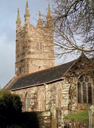
Solid masonry walls, particularly those of composite construction (figure 1), have performed extremely well over the past millennium. Most churches are built with two skins of stonework and a rubble core, and their towers are often very exposed. Despite enduring extremes of weather they still continue to function as originally intended. Over the centuries though, voids have developed within the core of the walls of many church towers which has resulted in the rapid conduction of water into the church after driving rain. One solution is to grout the core.
Recently English Heritage completed the Damp Towers research project which set out to assess the relative merits of grouting in such cases, and to establish a best practice method for carrying it out, even though the irreversible nature of the technique means it can be controversial. This article introduces the findings.
BACKGROUND
Driving rain problems are most acute in areas of high rainfall and exposure, so the research concentrated on church towers in the south west of England. A number of on-site repairs were studied, including grouting the whole tower at St John the Baptist, Stowford in Devon, which followed a series of laboratory tests. The research was prompted by the fact that problems of water ingress into some churches in the region were actually worse after repairs, and considerable sums of money were apparently being wasted. Investigations revealed that in most cases the repairs had focussed on repointing, carried out in a variety of mortar mixes, although some did include deep tamping and selective grouting where large voids were suspected. It was clear that repointing alone was not effective, regardless of the mix, if the wall still contained voids. This observation was corroborated by subsequent laboratory testing of trial walls in a driving rain chamber.
The Damp Towers research concentrated on the traditional repair techniques of rendering, pointing, grouting and internal plastering, using materials bound by lime. In practice, some stone replacement and reconstruction often took place, particularly where a core was substantially voided or the outer face had moved away, but this type of repair was not studied.
A considerable amount of research has been carried out on pointing mixes and much important and useful literature on renders and plasters is now available. But there is precious little written about grouting, despite this being a potentially invaluable technique that offers considerable benefits. In particular, grouting can obviate the need for substantial masonry reconstruction or the alternative treatment of rendering. Although there is considerable evidence that most towers were rendered, certainly before the 19th century, there is a general antipathy among parishioners to the visual loss of familiar masonry elevations.
So research was carried out into grouting, both in the laboratory and on site. Working closely with the architect and contractor to develop the specification and site practice for grouting the tower at St John the Baptist, Stowford also provided an opportunity to gather data on the effects of the work by monitoring moisture levels in the walls both during and afterwards.
THE PROBLEM
Wind-driven rain afflicts most churches on the western side of the UK. In the south west the rainfall levels are nearly three times that of the annual average for England and for exposed towers at high altitudes these can exceed 2,000mm. Most of the towers were built with hard, impermeable stones which means that the mortar joints and core deals with all the moisture movement. The quality of the core construction can also vary considerably. Many medieval towers were poorly built, containing varying degrees of voiding throughout the wall core. Some cores were simply an earth/ stone mix, occasionally blended with lime. Subsequent repairs may not have helped, for example the removal of protective renders or lime slurries and the widespread use of cement.
 |
|
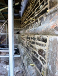
| Figure 2 St John the Baptist Church, Stowford in 2007 showing a very damp south elevation after a short storm. The tower is exposed to the prevailing weather and driving rain and has a long history of water ingress to the inside (illustrated below right). |
Other significant problems include determining what works have previously been carried out, the current state of the core, and how water is getting in. As church records are very inconsistent it is often extremely difficult to see what materials and techniques have been used. There are a great many non-destructive surveying techniques available today, but although many were tried in the research, none was able to provide reliable information on the extent or position of voids within a thick church wall. It is often presumed that water ingress will concentrate at areas where there is cracked or missing pointing, but the laboratory research showed clearly that capillary draw is more significant than the effect of wind pressure in water transport. In particular, most of the water was drawn in through perpendicular joints that appeared to be in sound condition.
WIND-DRIVEN RAIN AND WATER MOVEMENT
A great deal of research has been carried out by others on driving rain and water and moisture transport, but as little of this concentrated on mortar joints or solid wall buildings, specific tests were devised for laboratory testing at Sheffield Hallam University. The tests showed that a well-built wall with no voids will not let liquid water pass through to the inside even when fully saturated. However, as soon as the wall contains voids, water will transmit to the inside fairly quickly.
Walls wet up quickly but dry out slowly. To dry effectively there needs to be moving air at the surface (wind) that has a relative humidity of less than 100 per cent so that it can remove water molecules from the surface. A flow of water to the surface is therefore needed. Water can flow but unfortunately vapour travels much more slowly, so only a percentage of rain will dry out quickly from a wall. In a temperate climate like the UK’s all walls will contain moisture, but that is not a problem so long as most moisture does not flow to the inside but is allowed to evaporate away to the external air.
GROUTING
Grouting was devised as a technique for filling voids in the late 18th century and was used mainly on bridges and tunnels. It was employed more widely over the next two centuries on other buildings including churches, particularly in the 20th century. However, most of the grouts were based on liquid cement mixes and, more worryingly, there was no research or evidence on how the grouting was performing. Investigating would have meant invasive work that would only have been justified if there were obvious faults.
In the early 1990s English Heritage ran courses on grouting at its training centre at Fort Brockhurst. The practical work was carried out on purpose-made masonry ruins so, after grouting, the wall faces were taken down so that different grout mixes and application techniques could be evaluated. This allowed some measure of performance testing and showed that mixes based on hydraulic* lime, PFA* and bentonite* were capable of filling all voids and minimising shrinkage when injected using low-pressure pumps (words followed by an asterisk are defined in the glossary below). However, the performance and strength of grouts varied.
 |
|
| Water running down an interior wall at St John the Baptist Church, Stowford |
Developing an effective technique was also pursued further at Sheffield. This included how best to test for voids, how to ensure wetting would adequately remove loose debris in the core and minimise surface tension, and then how to determine the correct ratio of grout to water to ensure both an adequate flow and comprehensive filling.
After careful research to refine these techniques, the results at Sheffield showed that grouting could be the answer, as it could prevent driving rain from conducting water to the inside face. The next stage of the research was to monitor a church tower which was to be grouted, both during the work and again afterwards to assess its effectiveness and the rate at which the masonry joints and core of the tower dried out.
ST JOHN THE BAPTIST CHURCH, STOWFORD, DEVON
Stowford Church, situated near the Cornish border, had long suffered from the effects of driving rain (figure 2). Indeed, Gilbert Scott suggested in 1872 that the core should be grouted with liquid cement, the inside wall plastered with cement and that the external mortar joints be painted with a mix based on oil and litharge*. The 15th-century tower is 230 metres above sea level and is very exposed to the prevailing weather, receiving about 1,100mm of rain annually.
In addition to grant-aiding the repair work, English Heritage funded the research required for monitoring the moisture levels in the walls and commissioned Colin Burns to work closely with the architect, Simon Cartlidge, and the contractors, Carrek Conservation, to develop the specification and also establish some best practice principles for carrying out grouting. The first stage of the work was to carry out invasive tests to establish the extent of voiding in the core. These initial surveys clearly indicated substantial voids up to 30mm deep. This work, however, was not comprehensive enough to enable a specification to be prepared, so more detailed surveying was needed.
FINDING THE VOIDS
Determining the condition of the core and the position and depth of voids is very challenging. The best approach is to establish a grid that can be used to plot the voids and how they link. The voids are then found by carefully drilling holes in the wall and ‘feeling’ for them with the drill: when a void is reached a sudden lurch will be felt. With experience the operator can quickly gauge the depth of the void, and measuring the drill-bit will provide its location within the wall. That information can then be recorded on the grid. However, there is an art to the technique: if there is moisture in the wall and the drilling is too violent, slurry will adhere to the drill-bit preventing the operator from feeling the voids as they are encountered. The aim is to drill gently.
 |
|
| Figure 3 A typical grid which can be used for plotting voids: trial holes (in red) locate the voids (in blue) and their depth and extent are recorded on the grid, highlighting those that interconnect |
When the voids are flushed with water, those that interconnect can be recorded on the grid, so gradually a three-dimensional image can be built up (figure 3).
At Stowford, a scaffold was erected inside the church tower to enable a series of drill tests into the core of the wall. This consisted of 16mm diameter holes drilled 750mm deep, on a 1m-staggered grid. The tests showed that there was a run of 30-50mm deep voids at 250-300mm into the core of the wall with a further zone of 25mm deep voids at 500-600mm into the depth of the wall. This suggested voids immediately behind the outer facing stones and a second area of voiding towards the centre of the wall.
Because of the thickness of the walls and the difficulty of the grout becoming de-watered before it filled the voids, it was agreed that a pumped pressure system would be used rather than the more commonly used gravity system. A hand pump would be used, limiting the pressure and allowing the pump to wet the core of the wall thoroughly before grouting.
The specification attempted to ensure a systematic approach to the scope of repairs and to define a clear package of works, as follows:
- removal of the existing cement mortar pointing unless it was sound enough to contain the grout
- masonry repair and repointing in a hydraulic lime mortar of one part NHL3.5 to 2.5 parts aggregate (as there was virtually no historic mortar left, the mix was designed to be compatible with the granite and rubble masonry)
- drilling a staggered grid of 650-750mm deep 20mm diameter holes on each face of the tower at 1m horizontal and vertical centres, to clarify the number of insertion/ proving holes
- grout delivery to be limited to a pressure of 1.5 atmospheres and 1m vertical lifts every other day
- CMS Pozzament 1-5 Heritage Grout to be used; the specification was written to include detailed instructions for the grouting operations, based on previous experience, in order to obtain prices which reflected the work involved.
PREPARING THE WALLS
 |
|
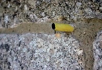
| Figure 4 20mm holes were drilled to accommodate lengths of hose to mark where voids were found; these would act as grouting points |
In order to pre-wet the core and to see which of the holes were linked to interconnected voids, water tanks with feed pipes were set up on the scaffold at the top of the tower, with connections at every level so that each level of the core could be flushed and flooded, starting at the bottom. A small electric motor pumped water to the top and kept the tanks full at all times.
Where the water escaped at the bottom point, the grid plan was updated to record the interconnecting void, and small plugs were inserted. These plugs marked the positions where the grout was to be introduced, at the bottom of the void in each case.
The condition of the cement pointing was generally not sound enough to allow it to remain as a barrier to escaping grout. So after the walls were tested for voids and flushed with water, the joints were raked out and repointed in advance of the grouting. Unusually, the pointing had to be done from the ground upwards. Grouting is never carried out downwards because air pockets could develop or loose debris in the core could block a narrow passage leaving a void below. When grouting upwards, any loose material is collected by the grout but falls out of suspension quickly so it does not impede the progress of the grout.
During the pointing, lengths of water hose were inserted to provide grouting points and to act as proving points during the grouting process (figure 4). Before grouting, water is again pumped in. The core cannot be over-wetted because when grouting starts, water will float on top of it. The water which precedes the grout pre-wets the surfaces within the core, ensuring a good flow.
THE GROUTING OPERATION
Grouting commences immediately after the channels have been flushed through. The grout is mixed with water in dustbins with a powered paddle. First a very runny grout is used. The manufacturer’s recommendation is 20 litres/25kg bag, but at Stowford a mix of 40-50 litres of water per bag was used for the first pass to make it even thinner. This is then followed by a heavier grout, but only experience can determine what this should be. The heavier grout will push the lighter grout out from larger holes and force it into those finer fissures that can satisfactorily accommodate the runnier mix. The excess water will appear to bleed through the external mortar joints, which of course, is their function.
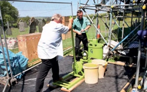
The grouting operation was carried out using a diaphragm pump. It is simple to use; merely pulling the handle pumps the grout (figure 5). It is relatively delicate so any resistance or blockage is quickly felt. It is rarely necessary to apply more than 25psi of pressure. It is essential to introduce the grout gently, because many of the voids are interconnected, so that the grout is travelling back and along, not just up. Pumping too violently will mean excessive loss of grout when leaks appear. A big advantage with this system is that the pump is operated from the ground at all times avoiding the need to lift it up the scaffold, although a converter is needed to make sure the grout is delivered by manageable hosepipes rather than the very heavy delivery hoses that come with the pump.
 |
|
| Figure 5 Architect Simon Cartlidge on the handle and Piers Denny of Carrek Conservation getting the feel of the diaphragm pump |
The optimum number of operatives is seven. Two are needed on the pump, two mix the grout, one manages the grouting point, and two look for leaks, one outside and the other inside, communicating with the pump operator by two-way radio.
A copper pipe is put into the grouting tube and grouting starts. When the grout starts to appear from one of the proving/grouting points (figure 6), a wooden dowel with cotton wool is put in to plug the hole. It is important to maintain the grout flow at the hole: if it is left even for short periods de-watering can occur and voids will be left. Any escaping grout on the wall face has to be cleaned off immediately to avoid staining, and hopefully glistening mortar joints should indicate de-watering taking place.
At Stowford, grouting was carried out for a day and then left for 24 hours to allow de-watering and reduction in volume to take place before continuing. Non-grouting days were spent continuing repointing up the tower. A minimum of one month was allowed for pointing mortars to set sufficiently in order to prevent the escape of grout. This was easily achieved because the grouting process was relatively slow.
Inspections were also carried out during the work, when the contractor was required to remove selected stones to ensure that the grout had satisfactorily filled the voids behind.
When the top of the tower was reached it was important to let the grout de-water and reduce in volume so the voids could be topped up adequately. In the event, however, not enough time was left and a void was created which led to water ingress, so a return visit was needed to re-grout this section.
On completion, 7.5 tonnes of grout had been injected into the core of the tower. From this it could be calculated that voiding within the tower had amounted to five per cent by volume.
SOME CONCLUSIONS
The moisture levels on all four elevations at each level of the tower were monitored using the oven-balance method (calculating moisture loss by weighing and drying timber dowels that have been inserted in the masonry). At the outset the west and south walls were running with water and therefore clearly saturated. After the work was finished the moisture levels still appeared to be very high (on account of the amount of water used) but within a year these had reduced down to less than 30 per cent.
 |
|
| Figure 6 When grout appears at the proving hole a wooden dowel and cotton wool are put in to plug the hole and prevent grout leaking out. |
Drying has continued and the architect’s recent quinquennial confirmed that the tower is dry with no reports of any moisture ingress. The grout clearly acts as an effective sponge. After one very wet month the moisture level in the south wall rose dramatically but by the following month this had evaporated to the outside and equilibrium water content was re-established.
Grouting may be highly effective, but it is certainly not a cheap option. At least seven operatives are required and once the scaffolding and all other costs are taken into consideration, the process is likely to cost £1,200-1,500 per square metre. In Stowford’s case rendering was considered unacceptable because it would have obscured the highly decorative facades of the tower, so grouting was the only remedial option available.
Grouting is also an invasive operation and is essentially irreversible. We do not yet know how effective it will remain. However, it does provide a remedial option that retains the appearance of the tower and one that should remain essentially maintenance-free (unlike rendering and pointing) for many decades to come.
~~~
Glossary
bentonite a clay mineral used in grouts to improve flow
hydraulic term describing the ability of a lime to set by chemical reaction with water, as well as by carbonation (a ‘non-hydraulic’ lime sets by carbonation alone)
litharge a form of lead monoxide (PbO) once commonly used in varnishes and glazes for its drying properties and its ochre colour
PFA pulverised fuel ash, a fine mineral by-product of burning pulverised coal in a power station; when added to a lime mortar PFA promotes a hydraulic set
Notes
[1] The results of English Heritage’s Damp Towers research project were presented at a conference in Exeter in April 2013. A summary of the papers will be published on the English Heritage website. The full results of the work are to be published in the Research Transactions series, together with a guidance note, later this year.