


19th-century Structural Ironwork in Buildings
Understanding, Care and Re-use
Michael Bussell
 |
|||
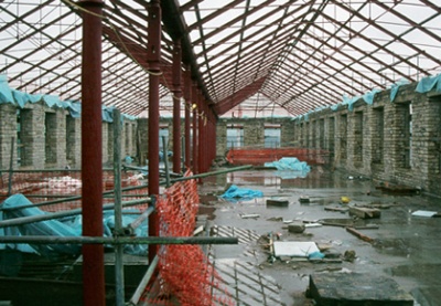
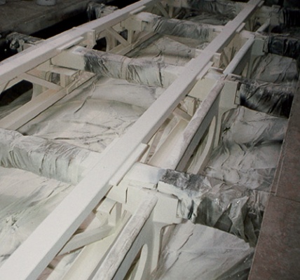
| Figure 1: The top floor of an 1860s textile mill in Huddersfield with cast iron columns and gutter beam, wrought iron roof trusses, and thick millstone grit external walls: the mill is shown here being adapted for use as a university teaching block. |
Decorative ironwork is rightly valued for its character, particularly when executed by skilled hands; but structural ironwork has in the past often been overlooked. Many prominent figures lobbied (unsuccessfully) to save the great masonry Arch at Euston Station in London, demolished in 1961-2, but barely a voice was raised as the early and delicate 1837 wrought iron roof trusses over the platforms went for scrap.
More recently, interest in understanding 19th-century structural ironwork has come from the welcome re-use of redundant buildings, alongside the need to assess the large stock of iron bridges for ever-increasing vehicle loads. Victorian warehouses, mills, and maltings are common iron-framed industrial building types to find wide re-use for apartments, offices, colleges, and other uses (see figure 1). Such structures are often listed, and current government guidance (such as PPS5) actively encourages new use instead of demolition.
HISTORIC BACKGROUND
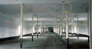
Cast iron beams and columns in buildings appeared in the 1790s, firstly in the multi-storey textile mills where workers and machines were crowded together (figure 2). Soon after, commercial and then naval dockyards were using structural iron in store-houses. Such buildings needed strong columns and beams to carry heavy machinery or stored materials. Stout timber sections were becoming scarce and expensive, and cast iron offered a versatile – and cheaper – alternative. Equally, the valuable contents made it important that these buildings were ‘fireproof’, particularly in mills where rags, lubricating oil-soaked timber floors and candles were a potentially inflammable combination. For a long time ‘fireproof’ was equated with ‘incombustible’, so a cast iron skeleton was provided in place of timber to support floors of brick arches covered with rubble and flagstones, or, less commonly, flagstones laid directly onto a more closely-spaced grid of iron beams (figure 3).
 |
||
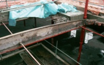
| Detail: the brick arches between the hump-backed cast iron beams are being broken out to accommodate a new staircase and lifts. |
Railways also quickly adopted iron for train shed roofs, from the largest spans right down to the smallest of platform canopies. Iron was soon found in every type of building: offices, hotels and grand houses displayed elegantly profiled cast iron columns, while wrought iron plate girders hidden above coffered ceilings spanned the larger public rooms; seaside piers stepped over the water with a timber deck on wrought iron girders and trusses bearing onto cast iron columns and piles; even terraced housing often used plain cylindrical cast iron posts to support bay windows, as Historic Scotland’s Guide for Practitioners 5: Scottish iron structures (1) clearly shows.
Leading ironfounders’ catalogues (2) offered an astonishing variety of off-the-shelf products, from railings and gates through beams, columns, and lamp-posts to complete canopies and conservatories. Foundries and fabricators were equally able to fulfil ‘bespoke’ orders for castings and wrought iron plate girders and trusses.
The main periods of structural use of cast and wrought iron in buildings can be summarised as follows:
Cast iron
- Beams and inclined roof rafters, etc – from the 1790s until c1870
- Columns – from the 1790s until c1910
Wrought iron
- I-section beams (small) and fabricated riveted plate girders and trusses – from c1850 until the 1890s
- Wrought iron columns – rare (cast iron columns were stronger and cheaper)
- Tie-rods and strapping to timber roof trusses – from late Medieval times until the 1890s
Steel
- Introduced c1885, dominant by c1900; had displaced both cast and wrought iron by 1914
In the second half of the 19th century, roof trusses were often ‘composite’: principal rafters of cast or wrought iron or timber were combined with a bottom boom and other tension members of wrought iron, and compressed diagonals of cast iron, often thickened with ‘entasis’ at mid-length to increase buckling resistance.
Whereas masonry wall and pier thicknesses and timber section sizes were commonly established by proven rule of thumb, iron structures were usually calculated for size, requiring awareness of loadings to be carried and of strength of materials. Civil engineers (a developing profession at this time) worked with what today are called materials scientists, testing materials and establishing ‘factors of safety’ on which to base their designs for major projects such as bridges and roofs. Architects, surveyors, ironfounders, fabricators and builders would often size beams using published tables based on these tests.
 |
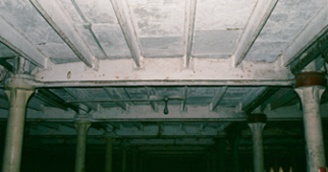 |
| Figure 2: Ditherington Mill (1796) near Shrewsbury in Shropshire, the world’s first multi-storey building with cast iron for both columns and beams. Originally a flax mill and subsequently a maltings, it is now Grade I listed but awaiting a new use. | Figure 3 The Quadrangle building in the former Naval Dockyard at Sheerness, Kent (1828, demolished): the flagstone floors were supported on a cast iron structure of fish-bellied secondary beams, hump-backed primary beams and hollow circular columns. |
IS IT CAST OR WROUGHT IRON?
To assess 19th-century ironwork it is essential to distinguish between cast and wrought iron, as they have significantly different properties.
Iron was produced, as it still is, from iron ore smelted in a blast furnace with burning charcoal (later coke) as a source of both heat and carbon, and limestone acting as a flux. With the temperature further raised by ‘blasts’ of air, at around 1150°C the iron liquefied with a carbon content of 4-4.5 per cent. This ratio produces the iron-carbon alloy with the lowest melting point (considerably below that of pure iron, c1535°C). After as much as possible of the ‘slag’ impurities had been drawn off, the molten iron was run onto a sand bed to cool and solidify as lumps of ‘pig iron’.
 |
||
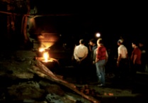
| Figure 4: Tapping a furnace with molten iron at about
1300°C for casting rainwater goods in a foundry
(long closed) in northern England 20 years ago. (The
photograph shows a relaxed approach to protective clothing that would be unthinkable today.) |
Cast iron was made from re-melted and refined pig iron, and shaped by casting. First, a permanent timber model of the component was prepared, from which single-use casting moulds could be made in sand. Known as a ‘pattern’, this model was about one per cent oversize to allow for shrinkage of the iron as it cooled and solidified. The pattern was packed with sand in a wooden box to make a mould, usually in two parts so that all iron surfaces would be enclosed in sand for a uniform finish. With the pattern removed, molten iron was poured into the mould. Vents allowed air to escape as the iron flowed to fill the mould. After cooling, the casting was released from the mould.
Wrought iron was made by re-melting pig
iron, with combustion gases and hot air being
drawn over the melt under a dome-shaped
roof to reflect air and heat downwards; as
oxygen came into contact with carbon in the
melted iron, the two elements combined as
carbon monoxide and burned off.
The iron was
raked over to expose it thoroughly to the hot
air, a hard job as diminishing carbon raised
the melting point of the iron, which became
increasingly stiff until it solidified as a spongy
mass of almost pure iron, free of carbon but
retaining some ‘slag’ inclusions. This, when
re-heated, was hammered to drive out more of
the slag, leaving the residue as thin threads.
The iron was further heated before rolling for
structural use into plates, rods, angles, and
(later) small I-sections. Thus, the iron is said
to have been ‘wrought’ or worked. The tedious
turning-over of the molten iron limited each
charge to about 200 kg, and man-handling the
resulting spongy mass kept each ‘ball’ to about
50 kg weight. Larger wrought iron sections
could be fire-welded together by re-heating
and forging, but this meant that every piece
of wrought iron was effectively ‘hand-made’.
A visual aid to distinguishing between the two forms of iron is that cast iron has a ‘grainy’ surface from the sand mould (although this may be masked by layers of paint), whereas wrought iron, being rolled, has a smoother surface (although this may be affected by corrosion, which roughens the surface). Cast iron was invariably joined by bolting; the hot-driven rivet, the fastener of choice for fabricated wrought iron sections (and later steel), was not suitable for joining cast iron as its contraction while cooling could crack the brittle metal.
 |
||
| Figure 5: A cast iron beam of c1860 after loading to failure at Manchester University: note the dull grey grainy texture of the material at the point of fracture and the larger bottom flange to compensate for the comparative weakness of cast iron in tension. |
Cast iron, as its name implies, can be made in any desired shape. This characteristic, widely exploited for decorative work, was also applied to more functional components, particularly brackets and columns, the latter often being modelled in classical forms. However, many cast iron columns were plain, either hollow circular, cruciform, or I-sectioned.
The relative weakness of cast iron in tension quickly led to the compensating adoption of enlarged bottom flanges in beams. For brick-arch floors in mills this larger flange was conveniently shaped with sloping sides to provide springing for the brickwork. Later, asymmetrical I-beams were introduced. A cast iron beam can often be distinguished by its thicker flanges and webs, generously-rounded internal corners (to avoid cracking in sharp re-entrants as the iron cooled), and a ‘hump-backed’ or ‘fish-bellied’ curved profile along its length, sometimes with a bowed-out bottom flange, to resist the higher bending stresses in midspan (figure 5). Wrought iron beams are either smaller rolled sections or compound girders with riveted plates and angles.
In cast iron columns, twin diametrically opposite lines are often seen along their length where iron had leaked out at the joint between the two halves of the horizontal mould (see figure 9).
STRUCTURAL PROPERTIES OF CAST AND WROUGHT IRON
How cast and wrought iron were made directly influenced their properties, and indeed their appearance. This aids identification and understanding of the material, which are essential prerequisites to its assessment.
The high carbon content in cast iron was in the form of graphite flakes, randomly oriented. In effect, these are voids in the iron with sharp corners, so that when subject to tension the iron would eventually fail abruptly in a brittle manner from cracking propagating from these corners. So, in tension, cast iron is relatively weak and fails in a brittle way. In compression, however, cast iron is actually stronger than mild steel.
In contrast, wrought iron is malleable and generally ductile (unless it has been overworked and not annealed by re-heating), with similar strengths in tension and compression – approximately the same strength as mild steel.
INVESTIGATION AND ASSESSMENT
It is always worth seeking drawings and other building records before on-site investigations are attempted; but even should an apparently full record of the structure be found it should always be spot-checked for possible errors or subsequent structural alterations.
The first on-site essential for a structural assessment is a dimensional survey from which construction weights, spans, heights, and section sizes can be obtained. This can be fairly straightforward where, as is commonly found, the members of an iron structure are fully exposed rather than being built into walls. However, some opening-up may be needed, for example to establish the dimensions of cast iron beams embedded in a brick-arch and rubble mill floor (remembering that the beam cross-section may well vary along its length, so both midspan and ends should be investigated).
 |
||
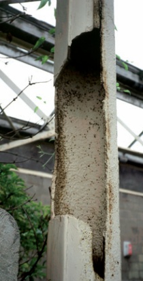
| Figure 6: A hexagonal hollow cast iron column, split by expansion of freezing water after the column (doubling as a rainwater down-pipe) became blocked while this disused 1851 station building at Rewley Road, Oxford stood derelict. Subsequently dismantled, restored and re-erected, the building is now a successful part of the Buckinghamshire Railway Centre near Aylesbury. | ||
 |
||
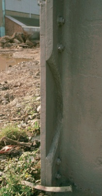
| Figure 7: A ‘pragmatic’ bolted steel plate repair to the
flange of a cast iron I-section: the column, in the former
Naval Dockyard at Chatham, Kent, was probably struck by a vehicle. |
The external diameter of hollow circular cast iron columns can be measured with callipers, while the wall thickness is found by drilling (non-percussively) small holes at three points equally spaced around the perimeter, at slightly different heights to avoid inducing a potentially weakened line, and pushing a bent wire in until the end, when withdrawn, snags. This gives the local wall thickness; three such measurements will define the internal wall profile. Slight non-concentricity is common, the internal core of the casting (usually sand, formed around a wrought iron bar) having moved a little in the mould as it was disturbed or ‘floated’ by the denser molten iron. Note that percussive drilling risks shattering the brittle cast iron: using a hammer drill could literally be lethal for both structure and driller.
The condition of the ironwork must be established. The principal enemy of structural iron, as for so many building materials, is water. Cast iron, as it happens, has good resistance to corrosion, thanks to the tough surface skin formed as the castings cooled. Indeed hollow circular columns – with or without an internal liner – were often used as down-pipes for roof drainage, especially in covered markets and other buildings with a large footprint. However, blockage occasionally results in water being trapped in the shaft, which if it freezes can fracture the column as it expands (figure 6). Inserting new internal liners in sound columns might be prudent.
Wrought iron, like steel, is more vulnerable to water damage. As with timber, special attention should be given to iron member ends built into external walls that can become saturated. Rust staining is an obvious clue, and as rust is larger in volume than the original iron, it often makes its presence known by ‘swelling’, for example where water has penetrated the narrow gaps at rivet positions in lattice girders. Reassuringly, if the rust is cleaned off, it will usually be found that the loss of section is substantially less than the superficial thickness of rust.
It should be remembered that 19th-century iron structures were built to Imperial dimensions, not metric. A cast iron column wall thickness of about 32mm or a wrought iron plate thickness of 19mm should be accepted as originally being 1¼ inches and ¾ inches respectively, as rounding to 30 and 20mm would impair the strength and stability assessment significantly.
This assessment, as at present and for the effects of intended alterations, will generally need a structural engineer who understands the very different characteristics of cast and wrought iron (3).
The assessment requires more space to describe than is available here; fuller guidance is available, for example in a Steel Construction Institute (SCI) guide (4). Two key points to note here are:
1 Cast iron, a brittle material lacking any significant ductility, must be assessed using ‘working’ loads and ‘permissible’ stresses – not by ‘limit-state’ principles as in current structural codes of practice for steel.
2 A suggested value for the yield strength of wrought iron is 220 N/mm² (a value long adopted in bridge appraisal guidance, and more recently in the SCI guide). The adopted yield strength for older steel (not subject to today’s more rigorous quality controls) is 230 N/mm² – less than 5 per cent higher than wrought iron. Thus, when assessing a structure from the 1880s-1890s ‘transition period’, when both wrought iron and steel were in use, metal sampling to distinguish these two materials is not essential. This saves money, avoiding the need for invasive sampling, important for heritage structures.
An assessment may bring the welcome news that the structure is adequate for present and future use. Alternatively, the need for repair or strengthening may be indicated. At this point a load test, typically to 25 per cent above the working load, might be suggested, to show that the structure has a greater capacity than is predicted by the (often necessarily) simplified calculations, but this needs to be carefully considered. Setting up and conducting a load test is slow and costly, and the results might merely confirm the bad news from the calculations. It may well be cheaper to bite the bullet and carry out necessary work.
REPAIR AND MAINTENANCE
Often, even a corroded structure requires only cleaning and repainting. Whether to strip paintwork back to bare metal requires thought. It will provide a clean surface and a good key for adhesion of the new paint scheme, but it involves the removal of older paintwork that may be of historic interest. More practically, this paint may contain lead and other toxic substances; its removal (after historical analysis if required) will typically require ‘shrouding’ of the work area, use of a wet-blast process, protective clothing, and safe capture and disposal of paint fragments. This will be expensive. Cleaning down and then ‘overcoating’ the existing paintwork may be a more practical alternative.
Like all building construction, structural ironwork benefits from observation of the long-established conservation principle of ‘stave off decay by daily care’. Regular inspection and clearing of gutters, and checks for signs of corrosion or other damage, will minimise the risk of more serious problems in future.
It may be necessary to repair damaged ironwork, or strengthen it to carry increased loading. An honest local repair may suffice – for example, a small ‘patch plate’ bolted onto the damaged flange of a cast iron column (figure 7). Alternatively, on the principle of ‘reversible intervention’, the existing structure may be augmented with new work rather than replaced. A notable example of this is the clear-span floor of 1827 over the Grade I listed King’s Library in the British Museum, London, carried on ‘hump-backed’ cast iron girders with pierced webs spanning almost 15 metres. An assessment (5) showed these to be under-strength for future use. Rather than replace them with new beams, additional welded tubular steel girders were introduced alongside the original girders, to share the loading between them (figure 8).
Welding is seldom a suitable connection method for structural repairs to either cast or wrought iron. With the lower melting point of cast iron, the heat generated locally in welding risks destroying the existing profile of the element. Fillet welding is not suitable for wrought iron, with its laminar nature, as the newly-welded element is liable to detach from the layered iron when loaded; butt welding requires extensive on-site preparation of the metal. In general, bolting or clamping are the most suitable connecting methods in structural repair work.
 |
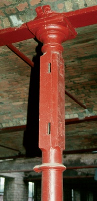 |
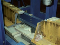
| Figure 8: (above left) Structural intervention at the King’s Library in the British Museum in London: the addition of new tubular steel trusses alongside the 1827 hump-backed cast iron girders allowed the floor loadings to be shared, thereby avoiding the need to remove the original girders. Figure 9 (above right) A cast iron column in a Huddersfield textile mill after the application of an intumescent coating; note prominent ‘seam’ on near face of column where a little iron seeped into the joint between the two halves of the mould when the column was being cast horizontally. | |
FIRE PROTECTION
In the 19th century, iron and masonry structures, being non-combustible, were considered to be ‘fireproof’. Nowadays, periods of fire resistance are defined to allow occupants to escape and to provide reasonable time to safely fight the fire. This usually demands applied structural fire protection, unless a fire engineering assessment shows this to be unnecessary. Cast iron beams embedded in a brick-arch and rubble mill floor, for example, can often be shown to have adequate resistance, as the temperature rise of the exposed bottom beam flanges will be retarded by the ‘heat sink’ effect of the massive floor construction. However, free-standing columns and down-standing beams are likely to need applied protection. A widely-favoured method is the intumescent coating, which swells up when exposed to heat, forming a closed-cell barrier that slows the temperature rise of the structural element. Thin-film coatings are available that will allow the profile of decorative cast ironwork to remain visible (figure 9). Other forms of applied protection include boarding and sprayed mineral fibre, although these inevitably mask the structural outlines.
As well as being valued for its historic significance and for its functional role, early structural ironwork is often an important part of the aesthetics of a converted or adapted building. Once understood and assessed, it can usually be maintained as it stands, or adapted if necessary to ensure a continued useful life.
~~~
References
(1) Tom Swailes, Guide for Practitioners 5: Scottish iron structures, Historic Scotland, 2006
(2) David S Mitchell (editor), Macfarlane’s Castings: Walter Macfarlane & Co, Saracen Foundry, Glasgow, Catalogue, sixth edition, two volumes, Historic Scotland, 2009
(3) CARE, the Conservation Accreditation Register for Engineers, see www.careregister.org.uk
(4) M Bussell, Appraisal of existing iron and steel structures, Steel Construction Institute, 1997
(5) R E Slade and C Playle, ‘The British Museum: upgrading the floor over the King’s Library’, The Structural Engineer, 73(12), 20 June 1995, 193-199