


Fabric-friendly Heating
Dario Camuffo
 |
||
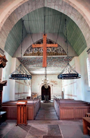
| Electrically-fed infrared emitters were installed inside the chandeliers in this church to provide heating to the upper bodies of churchgoers using the front pews. The heating project, led by Tor Broström of the University of Gotland, Sweden, also incorporated heating foils and heated carpets fitted inside the box pews to warm the feet and lower body. (Photo: Tor Broström) |
In 2002 an EU-funded programme, the Friendly Heating Project, started to examine the impact of heating systems on historic church paintings, statuary, furniture and fabric. At that time, published research on church heating was limited to a handful of case studies. Only one overview of all heating systems existed, the very useful Council for the Care of Churches publication, Heating your Church (W Bordass and C Bemrose, 1996). However, this overview was concerned with general issues such as safety and costs. It did not examine the potential impact of heating on historic buildings and the often precious artefacts they contain. Until recently, the prevailing view has been, as ED Mills wrote in 1959, that: ‘Church heating systems should be designed for economical running, the minimum of labour in servicing and maintenance, unobtrusive appearance and efficiency as a heating medium’. Heritage conservation issues have often been ignored.
Objects continually interact with their environments and these interactions are governed, in particular, by temperature and relative humidity (RH), which ultimately control the moisture content in materials. The current condition of a historic object is determined by a lifetime of these interactions, including adaptation and acclimatisation. There is, therefore, a natural set of environmental conditions experienced during the history of an artefact: its ‘historical climate’.
The Friendly Heating Project (2002-2005) was designed to carefully study and evaluate the characteristics of all heating systems, especially their potential impact on a variety of historical artworks, in order to devise and test the best system. The goal was to preserve artworks in their historical climate while providing compatible comfort heating for the congregation.
This article summarises the main outcomes of the Friendly Heating Project and more recent studies to help congregations find the most appropriate solution for the conservation of the cultural heritage kept in their churches.
REVERSIBILITY
Given the limits of technology, rising safety standards and the demand for ever greater levels of comfort, no heating system can be expected to operate for more than 30 years. Inevitably, any installation requires intervention and potential damage to church fabric. For example, installing radiant floor heating means removing the whole floor and the loss of its historic fabric. Further serious problems arise if tombstones or archaeological remains are present. Warm air heating involves the excavation of large ducts to blow and extract air. Internal gas combustion heating requires piping for gas supply and the insertion of ventilation holes. Hot water radiators are fed by large insulated pipes installed inside the masonry.
Repeatedly changing heating systems is not sustainable, especially for old buildings: invasive work cannot be repeated every few decades. Therefore, the choice of heating system needs to prioritise minimal intervention and reversibility, ensuring that obsolete systems can be easily removed and the building returned to its prior condition.
The two main types of heating, central heating and local heating, are discussed in more detail in the following sections.
CENTRAL HEATING
Central heating is designed to provide even heat distribution within the whole building, at the same time supplying heat to the building envelope (Figure 1a). It is used to reach the desired comfort level, or to provide background heating to the building in order to prevent very low temperatures and frost. The most common use is for large building volumes, and the most popular systems are radiators, warm-air heating, natural or forced-air convectors, electric or fuel stoves and underfloor heating.
In terms of conserving historic artefacts we should note that each heating operation forces the indoor climate to depart markedly from the historical climate, causing a potentially harmful situation. Critical factors are: sharp peaks in air temperature and sudden drops in RH, which is a common problem with warm air heating installations for occasional use; or cyclical changes in both air temperature and RH where systems are used to provide gentle background heating or where large inertia systems (such as underfloor heating) are used; or excessively low RH where continuous heating is required in cold regions.
 |
||
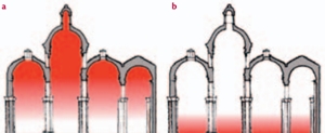
| Figure 1 The two heating strategies: (a) central heating aims to provide even heat distribution throughout the building while also supplying heat to the building envelope. Most of the heat is accumulated in the upper part of the building (b) local heating aims to produce the best radiant temperature within the occupied area of the church only, with some local increase in air temperature and minimum draughts. The rest of the building remains almost unaffected and preserves or remains close to its historical climate. |
Unfortunately, very low RH cannot be mitigated by the addition of moisture vaporised into the air. To understand the problem it is necessary to consider separately the thermodynamics of intermittent and continuous operations. (Technically, this should be explained in terms of ‘dew point’, the temperature at which moisture precipitates from humid air, but it can be more easily understood by considering surface conditions alone, in terms of RH reached at the interface between the air and the object surface.)
In the case of intermittent heating, when the system is operating, paintings on canvas, tapestry and the surface of wooden artefacts will closely follow the sharp increase in air temperature and the RH at the interface will be exceedingly low, causing some surface drying. In contrast, frescoes, marble statues, masonry and other items with a large inertia will remain cold: initially, the surface RH will remain normal, but as the air temperature in the upper parts of the interior rises, moisture evaporating from the ceiling and the upper masonry can be carried by convection currents to cooler surfaces below. Here it is supplemented by moisture released from people, causing the RH at the interface to become very high (Camuffo et al 2010). As a result, any addition of moisture into the air will be beneficial to objects with a short-term inertia, but it will have a negative impact on objects with a long-term inertia.
In the case of continuous heating, all surfaces will reach equilibrium with steady but different temperature levels determined by internal heat distribution, leakage and heat loss via conductivity, for example. Once again, the addition of moisture into the dry air will be beneficial to the warmest surfaces but will have a negative impact on the coldest ones, where condensation may occur, potentially generating moulds or affecting masonry by triggering salt crystallisation cycles.
Central heating requires a huge amount of energy, a large proportion of which is wasted through thermal bridges, leakage and storage in the building envelope. Typically historic churches are not energy-efficient buildings and their scope for improvement is limited. Being based on the dispersion of heat, central heating is not very effective in this type of building, where there are so many potential sources of heat loss. With central heating, people benefit from only a small proportion of the total power supply, meaning the whole system has low efficiency.
LOCAL HEATING
Local heating is designed to produce the best radiant temperature only in the occupied parts of the building, with some local increase in air temperature and a minimum of draughts (Figure 1b). The rest of the church volume remains almost unaffected and preserves its historical climate, or departs from it only slightly. Local heating is most commonly used for small congregations and building volumes, for example small churches or specific parts of them which are in use. The most popular systems are radiant heating from infrared (IR) emitters located overhead, on side walls or at floor level; and pew heating using electric panels, tubular heaters, water pipes or radiators, or heated carpets (discussed in more detail below).
This type of heating system disperses a small amount of heat in targeted areas, while the building envelope and historic furnishings or artworks are exposed to little or no change in temperature. Outside the moderately heated occupied area, the RH remains almost unaffected.
Because it minimises the dispersion of heat, local heating is suitable for non-energy-efficient historic buildings thanks to the smaller loss of heat. Less energy and therefore less fuel is required. With local heating, people benefit from a large proportion of the total power supply – the system has high efficiency.
HEATING SOLUTIONS
The Friendly Heating Project demonstrated that local heating was the best form of heating for historic churches, but it was necessary to conduct further research to determine how best to reduce heat dispersion and improve the limited comfort that local heating typically provides. In recent tests the best results were obtained with gentle IR radiation emitted from low-temperature sources including low-temperature heating foils, heated glass units and heated carpets.
 |
||
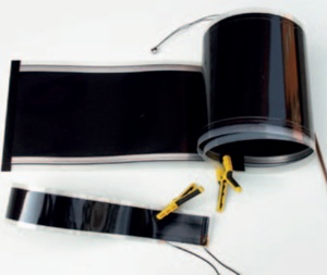
| Figure 2 Heating foils: the wider strip was used for underneath the pews, the narrower one was used for the kneeling pad and pew-back hand-heaters. |
The gentle emission of mild or warm air from fan heaters for example was quickly excluded because warm air cannot be buoyancy controlled: it rises quickly, escaping from the occupied area and being dispersed aloft, with little benefit for churchgoers. In particular, churchgoers affected by warm-cold fluctuations feel an unpleasant sensation and they may prefer no heating to draughts alternating warm and cold air.
Heating should be modular, that is: the space to be heated should be divided into independent parts that can be operated separately, or together. For instance, in the case of a few people attending a celebration, the front pews can be heated independently. Modular heating reduces the heat dispersed into the church and reduces costs.
The Friendly Heating Project and related subsequent research (see recommended reading, Camuffo (2007, 2010), Conference on Energy Efficiency in Historic Buildings (2011)) identified a number of different solutions, each of them for a specific church application, taking into account the different architecture, lay-out and liturgy associated with different religious communities, from the pew arrangement typical of the Catholic Church, to the box pews popular in the Lutheran Church, or the standing congregation typical of the Orthodox Church. Similarly, account had to be taken of the position of celebrants, choirs, organists and so on.
Heating foils (Figure 2) proved to be a particularly useful and versatile option. Wafer-thin units can be used to provide pew heating, to form horizontal, vertical or cylindrical heating panels adaptable to any surface, or under the altar-cloth. The heating foil is made of an electrically heated layer of graphite in microgranules deposited on a fibreglass backing and then sealed between two plastic foils. When an electric current is passed through the conductive graphite layer, the electrical energy is converted into heat energy and the layer heats up. When the foil is heated, it expands and the increased width increases the distance between granules. As a result, the electrical resistance increases with the foil temperature and reduces the current intensity so the maximum temperature of the foil is self-regulated at ‘built-in’ pre-set levels. This self-regulation provides a natural cut-out, preventing the risk of fire or contact burns. A thermostat is added for further fine regulation and safety, but is not necessary.
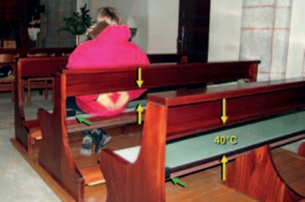
Pew heating is generally not very comfortable, especially where the building envelope is at a very low temperature. It was found, however, that thermal comfort could be improved with an ergonomic combination of foil heat sources distributed in the part of the church that is in use, fitted beneath kneeling pads and seats, and on the back of seats (Figure 4). Feet are the most sensitive parts of the body exposed to cold, and the air near the floor is the coldest, renewed every time an exterior door is opened. A band of heating foil was introduced under the kneeling pad to heat the occupant’s feet from the upper part of the shoe, which is the most efficient solution. The heaters below the seats heat the calves of the person sitting on that bench, and the legs of the person sitting on the pew behind. The heating foil band placed in the back of the pews is designed to heat churchgoers’ hands when they are sitting and their chests when they are kneeling.
 |
 |
|
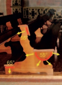
| Figure 3 These transparent but robust glass heating units (yellow arrows) provide a comfortable temperature to the back and hands. Twin thermostat arrays are housed inside the marked boxes (green arrows). | Figure 4 Location and temperature of heating units fixed to pews as part of the Friendly Heating Project |
The heaters have been designed to meet the physiological needs of the various parts of the body so feet are the first priority, then legs, and the torso last as this should be adequately covered with heavy clothing. The range of temperatures achieved was between 40°C and 70°C.
All heating foils should be protected against accidents and vandalism. The preferred solution is a fine stainless steel mesh placed in front of the foil and, on the back of the foil, a reflecting aluminium foil and thermal insulation to avoid back dispersion. The steel mesh will reflect most of the radiation impinging on it as it has a very low IR absorbance (typically around 7%). The mesh will assume an intermediate temperature between the heating foil and the air, and meets safety requirements by becoming warm but never hot.
Glass heating units (Figure 3) can be used on the back of pews, or in front of cold windows, or mounted on the walls at the level of a sitting person. In such cases, the heaters below the seats are not necessary and should not be used. The glass units are made of very strong tempered glass which contains a transparent submicrometric layer of sputtered metal oxides. The electrical resistance of the metal oxides causes them to heat up when electric power is applied. A thermostat maintains air temperature at the desired level (usually 40°C) and a second thermostat guarantees safety even in the case of failure of the first thermostat. The glass units provide thermal comfort by means of IR radiation or direct contact with the back or the hands. In front of windows or walls they may counteract cold draughts passing along cold surfaces. The units can attain an excellent safety standard and resistance, so they don’t need to be contoured by a support frame. They are also easy to clean and maintain.
 |
||
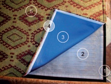
| Figure 5 Heated carpet composed of: (1) insulating layer on the bottom to avoid heat dispersion to the floor (2) heating element (3) protective layer forming the underside of the upper cover (4) velcro fastener allowing removal of the upper layer for cleaning or replacement (5) upper cover resembling conventional carpet |
Heated carpet (Figure 5) incorporates a heating foil or element placed between an insulating layer on the bottom to avoid heat dispersion to the floor and a carpet-like layer on the top. The top layer should protect the heating foil against mechanical damage by sharp objects, fire, water, etc. The surface temperature should be low (typically 20°C) and should provide comfort to feet but is unable to heat the rest of the body, which should be heated with other sources such as remote IR emitters (see title illustration). The area of the church used by the celebrant is warmed with heated carpets and remote IR emitters from both sides to produce even heat distribution. (For more details about these solutions, see Camuffo et al, 2007, 2010).
Examples of how these concepts can be applied to box pews are shown in the title illustration and in Figure 4. Inside the box pews, some heat sources (heating foils and/or carpets for example) are located, but the envelope is too cold to provide satisfactory comfort. The box provides a thermal island, protected against lateral draughts, but the churchgoer’s face is exposed to the cold. For this reason chandeliers have been installed which contain electrically-fed IR emitters to provide some benefit to the upper body. The aim is to supply a gentle distribution of heat focused to warm those parts of the body that are most susceptible or exposed to the cold, rather than overheating one area of the body while underheating the rest.
CONCLUSIONS
Unfortunately, the environmental conditions that are most suitable for historic churches and their contents are less suitable in terms of the comfort of churchgoers. With low level heating, these divergent needs may not come into conflict, but when the environment becomes uncomfortably cold, or heating is maintained at too high a temperature, the two requirements conflict and a compromise between the two needs to be reached. The ‘compromise’ temperature may depend on the vulnerability and value of the church fabric and furnishings.
However, if the requirements of sustainability or fabric preservation mean that the degree of heating has to be limited, churchgoers don’t necessarily need to suffer. Intelligent and carefully targeted use of heating should mitigate the cold environment and, as always, churchgoers should be prepared to dress accordingly.
The Friendly Heating Project and later related research produced invaluable analysis and evaluation of all kinds of heaters from the point of view of the conservation of cultural heritage preserved in churches. Among the project’s general conclusions, the following points are worth stressing:
- reversibility of the installation should be considered a priority
- conservation and energy saving are mutually compatible but result in temperatures that may be uncomfortable for the congregation
- a compromise between the opposing needs of conservation and comfort is necessary; in the case of conflict, conservation should take priority
- local heating is more energy-efficient than central heating
- if intermittent heating is required, local heating systems are less harmful to historic fabric than central heating
- improving envelope insulation, reducing heat leakage and wearing warm clothes should always be the first step. Only afterwards should the other heating options be explored.
These basic concepts inform the European Committee for Standardization’s new standard: Conservation of cultural property – Indoor climate – Part 1: Guidelines for heating churches, chapels and other places of worship (prEN 15759-1:2011).
~~~
Recommended Reading
W Bordass and C Bemrose, Heating your Church, Council for the Care of Churches, Church House Publishing, London, 1996
D Camuffo, Microclimate for Cultural Heritage, Developments in Atmospheric Science 23, Elsevier, Amsterdam, 1998
D Camuffo et al, Church heating and preservation of the cultural heritage: a practical guide to the pros and cons of various heating systems, Electa Mondadori, Milano, 2007
D Camuffo et al, ‘An advanced church heating system favourable to artworks: a contribution to European standardisation’, Journal of Cultural Heritage, Vol 11, No 2, 2010
Conference proceedings, Conference on Energy Efficiency in Historic Buildings, organised by the Swedish Energy Agency, Gotland University, Swedish National Heritage Board and Churches of Sweden, Visby, 9–11 February 2011
Conservation of Cultural Property – Specifications for temperature and relative humidity to limit climate-induced mechanical damage in organic hygroscopic materials (EN 15757:2010), European Committee for Standardization, Brussels
ED Mills, The Modern Church, Architectural Press, Princeton, 1959
L Samek et al, ‘The impact of electric overhead radiant heating on the indoor environment of historic churches’, Journal of Cultural Heritage, Vol 8, No 4, 2007
Acknowledgements
This article reports the findings of the EU funded research Friendly Heating Project (EVK4-CT-2001-00067) and disseminates the results of the activity of CEN/TC346 WG4 concerning European standardisation.