


Lead Gutters
Common Defects
Steve Hempstock
 |
|
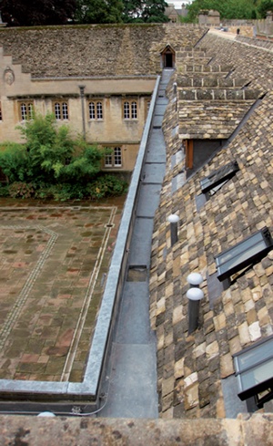
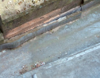
| Simple parapet gutter at Corpus Christi College |
Lead linings are commonly found in the valleys between pitched roofs and behind masonry parapets. Defects here often seep quietly for months or even years, providing the ideal conditions for dry rot, wet rot, insect infestations and other forms of decay. The correct use of lead is crucial to their success, and if correctly detailed, these linings can last for centuries.
Lead sheet is the earliest known metal to be used as a roofing material, and with a proven lifespan in excess of 100 years it continues to be used today. From early medieval times many churches and fine houses used sheet lead which had been cast on a bed of sand for covering their roofs, and sand cast sheet continued to be used exclusively until the 18th century, when milled lead (now known as rolled lead) began to be used for roofing.
Today, there are three types of lead sheet manufactured for use in construction, with significant differences in each end product that can affect performance.
Rolled lead sheet (previously referred to as milled lead) is the most commonly used and widely produced. As its name suggests, it is made on a rolling mill that controls the thickness of the finished sheet to within fine tolerances (any point on the sheet must be within +/- 5% of the standard thickness). Rolled lead is the only type of sheet that is produced to a European Standard, BSEN12588, which as well as regulating dimensional tolerances also states the amount of permitted inclusions (of copper, tin, antimony, etc) in the lead that provides the feedstock to the rolling mill. Thickness are defined by codes with Code 4 (1.8mm) to Code 8 (3.55mm) the most commonly used. Rolled lead’s uniform metallurgical grain structure helps it to resist fatigue cracking from thermal movement.
Sand cast sheet is still made using the oldest method of manufacture, as it remains in demand for restoration and refurbishment work where like-for-like replacement is required. This traditional method cannot produce the fine thickness tolerances achieved by modern rolling mills and is normally produced in the thicker codes of sheet. Nevertheless, the British Standards Institute recognises the product in BS6915 (Design and construction of fully supported lead sheet roof and wall coverings – Code of Practice) as it has proved during its centuries of use to perform just as well as rolled lead sheet.
Machine cast sheet is the latest manufacturing form, originally introduced to the UK as a sound attenuation product and adapted for roofing in the 1980s. Machine cast sheet is not made to a European Standard as it is not produced to within the +/-5 per cent thickness tolerances required of BS/EN12588 material. In addition, the metallurgical consistency of machine cast is different to rolled sheet as it does not have a uniformly distributed grain structure within the sheet.
Users of machine cast sheet should seek working and fixing recommendations from the manufacturers which have been shown to be adequate through evidence of use.
PROPERTIES
Lead is a silvery metal which rapidly turns a dull grey when exposed to the atmosphere. This patina is relatively inert and extremely durable, and is one of the two main reasons why lead sheet makes such an excellent roof covering. The other is that the sheets are easily shaped by basic hand tools. The result is an unrivalled weatherproofing material which can, in the hands of a skilled and knowledgeable craftsman be shaped to fit, protect and preserve any detail of architectural significance, no matter how complex.
However, this same malleability creates problems for the unwary. Being a soft metal, lead sheet reacts to thermal changes, expanding in warm sunlight and contracting when temperatures cool. Properly allowing for this thermal movement when sizing and fixing any detail is critical to the long term performance of the sheet, which is why only a skilled installer should be used.
DESIGN
Lead sheet in general has an excellent performance record, but when failures do occur, it is normally the result of incorrect sizing and fixing, restricting natural thermal movement.
Most lead details involve a piece of lead sheet ‘hanging’ in some way on its fixings; even a roof bay fitted to a fall of only 1 in 80 tries to ‘creep’ down the slope, restrained by the fixings at the head of the panel. Head fixings prevent creep, and intermediate fixings (clips) prevent wind lift, both of which need to be fitted correctly to allow free thermal movement.
 |
||
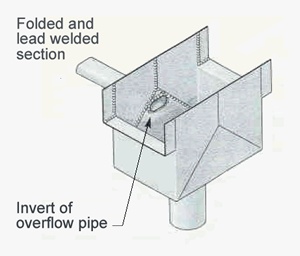
| The Lead Sheet Association's recommended detail for an overflow pipe from a sump (Reproduced from The Lead Sheet Manual by kind permission of the Lead Sheet Association) | ||
 |
||
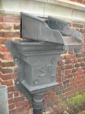
| An alternative overflow detail where the parapet gutter discharges horizontally through the parapet wall: the step ensures that under normal conditions the spout discharges into the hopper below. In the event of a blockage, water will cascade over the step and clear of the fabric safely, in a highly visible way, alerting owners to the problem. | ||
 |
||
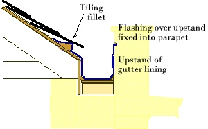
| A typical section through a parapet gutter (not to scale) |
Thermal movement is a natural occurrence in lead sheet, caused by the variation in day and night temperatures. Extreme variations occur in spring and autumn, when a hot sunny day can be followed by a very cold night. If a long sheet of lead is fixed at both ends, natural expansion and contraction will result in the sheet buckling regularly at the same point, causing fatigue lines to appear as the material begins to loose its elasticity. Cracks follow, allowing water ingress.
Other issues affecting the performance of the sheet which the architect or specifier needs to be aware of include the type of substructure on which the sheet is laid, the positioning of the drips (steps) resulting in trapped bays, the sizing of joints (drips and laps) and general faults in the design of the installation.
SUBSTRUCTURE
A good quality substructure is essential. Rough sawn, square edged softwood board is the preferred material. The boards should be regularised to ensure that the surface is even as, once the lead settles onto the substrate, any large surface discrepancies will tend to show through the sheet.
Green oak can cause corrosion as tannin (tannic acid) contained within the oak attacks the lead. If the lead is laid directly onto green oak a separating membrane should be used such as a Class A building paper or, in certain circumstances, a bitumen paint may be suitable, particularly under lead flashings. If green oak is fixed above leadwork, tannic acid can leech onto the lead, and while in this situation the tannic acid does not harm the lead, it can cause unsightly staining and discolouration.
Where lead sheet is laid on masonry, it is essential to ensure that the surface is smooth, as sharp edges could perforate the lead when thermal movement occurs. An underlay of Class A building paper or geotextile matting is best.
It is important to remember that lead sheet will settle into any surface imperfections in the substrate. It must therefore be laid to a constant fall with no depressions which would allow rain water to collect. Where ponding occurs, high winds can then force the collected water back up and over steps and rolls into the substructure.
GUTTER LININGS
When considering parapet gutters or tapering valley gutters on historic buildings, it is usual to specify Code 7 or Code 8. Very often, however, the existing configuration will have bay lengths in excess of the current recommended limits in the BS6915 Code of Practice. It is also regularly found that drip heights do not conform to the Code of Practice and it is therefore essential that the contractor engaged to carry out the leadwork has sufficient knowledge and experience to recognise such problems and provide an alternative design to enable the installation to be completed correctly.
Failures caused by oversized gutters normally present themselves first as a ridge across the sole of the gutter before a fatigue crack actually appears. A similar effect is caused by over fixing correctly sized sheet.
Gutter failures can therefore be the result of any of the following common causes.
Over-sizing (in width and/or length) It should be remembered that the overall maximum width of a gutter can be increased, provided the overall length from drip to drip is reduced. However, the maximum recommended length of a bay cannot be increased, even if the width is reduced (guidance from a specialist is strongly recommended).
Over-fixing Gutter bays should be fixed at the head, into the rebate of the step. If the fall exceeds 3° additional fixings will also be required at the base of the drip. Gutter bays can also be fixed for the first third of the bay length through the upstand (to the parapet wall for example). However, if the fixings are taken beyond this point, then even a correctly sized bay will ultimately fail, with fatigue cracks appearing across the sole of the gutter. The fixing heads should be sealed by either welding lead patches over or, in the case of a hot work ban on the site, using a lead patch fixed by a suitable ‘liquid metal’ resin.
Stone slates If the pitched roof covering is stone slate, such as York stone, then it is possible the weight of the stone on the lead where it turns onto the tilting fillet will act in much the same way as if there were mechanical fixings down the length of the bay. It is advisable in this situation to stop the gutter wall just below the top edge of the fillet and introduce a separate cover flashing lapped over the gutter wall from under the stone slates, thus allowing the bay to expand freely.
Trapped bay Perhaps a slightly less obvious potential failure is a trapped bay. This simply means a gutter bay that is fixed into the rebate at one end and turns a corner at the bottom end before the drip detail. In this situation, if at all possible, the drip should be relocated before the bay turns the corner. However, where this is not possible it is essential (although not ideal) to leave the bay short of the corner so that during thermal expansion the lead can move up to the wall freely.
Run-off from lichen and moss It is advisable for any roof or gutter bay detail to have a sacrificial flashing installed to catch the run-off from a slate or tiled roof that has a covering of lichen or moss, as it is mildly acidic and corrodes the lead at the point of contact. The sacrificial flashing should be fixed by clips below the edge of the slates so that it can be easily replaced.
GUTTER OUTLETS
The sizing and positioning of the outlet is another area that needs careful consideration. In historic buildings with a parapet, the water from the parapet gutters or valley gutter collects behind the parapet in a sump. Traditionally, there is only one outlet, usually a lead pipe passing through the masonry to an external rainwater downpipe, but in some cases there is an internal rainwater downpipe instead. In both situations it is essential to introduce an external overflow pipe or welded chute, as leaves and other matter that collect here cause restrictions and partial blockages: the gutter area fills to the point where water starts seeping into the underlying roof structure.
 |
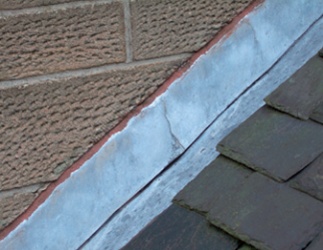 |
||
| Above left: A flashing which was inadequately fixed into the parapet wall has fallen out, exposing the upstand of the gutter lining. Above right: A flashing which is fixed into masonry must have lapped joints at least every 1.5 metres, as otherwise it will be unable to tolerate the amount of thermal movement, causing it to buckle and eventually crack, as here. | |||
FLASHINGS
Parapet gutters invariably have horizontal flashings on the parapet side, lapped over the upstand. The flashings are wedged or screw fixed into joints in the parapet, with the result that they are unable to expand or contract along this side. Lengths of flashing should therefore be kept short to avoid excessive movement, with laps every 1,500mm. Movement in longer lengths will result in a crease forming when the material expands. Over time vertical fatigue lines form and eventually fracture, allowing water ingress. In such circumstances it is not necessary to renew the entire flashing, as a small piece of lead can be wedged and pointed into the flashing joint, lapping over both sides of the crack by at least 100mm.
Further problems can occur when a flashing that is turned into a masonry joint springs out, allowing water ingress. This can happen through inadequate fixings or because the turn in to the masonry joint is too shallow. BS6915 Code of Practice requires a 25mm turn-in, but this should be regarded as a minimum. When preparing flashing pieces with a fold to be turned into a masonry joint, the deeper it is turned in, the better the fixing will be.
DEEP FLASHINGS AND VERTICAL CLADDING
A flashing of 250mm ‘girth’ (the full width of the sheet, including bends) can have anything up to 150mm of unprotected substructure behind it, once the 25mm minimum turn-in and the 75mm minimum lap over the upstand to the roof or gutter is taken into account. A lap of 100mm between lengths of flashing would not be adequate in this instance because wind driven rain will travel sideways at roughly 45° in a lap and water will therefore reach the substructure before it reaches the top of the gutter upstand. The installer should always check that the lap is slightly more than equal to the exposed substrate, and in this instance a 150mm lap should be used. This is usually an unseen potential failure point, but easily checked by lifting the overcloak and measuring the lap.
If the flashing over an upstand is required to be more than 250mm, then the experienced installer will use a combination of a standard cladding detail with a cap flashing. The cladding should be jointed by vertical rolls, or more commonly welts, in order to protect the substructure. The detail is finished with a cap flashing, turned and lapped into the chase and then pointed.
It is essential with vertical cladding to ensure the fixing is correct. A common fault is the head fixing, which should be determined by the size and weight (thickness) of the panel. Normally Codes 4 and 5 are used for vertical cladding, and panels under 500mm high can be adequately secured with one row of nails fixed 50mm apart. For larger panels two rows of nails are required, 75mm apart with staggered centres, aligned 25mm and 50mm from the top edge. Panels using Code 7 or 8 should be fixed with three rows of nails.
Where vertical cladding has been inadequately fixed at the head, problems present themselves in the form of slipped panels revealing elongated fixing holes just below the bottom edge of the upper panel or cap flashing. Over-fixing invariably results in bulging panels where movement has been restricted.
Clips are an essential element of vertical cladding and should be fitted to the bottom edge to prevent wind lift (rather than to provide additional fixing). The lower 2/3 of a vertical cladding panel must be left free to expand and contract with natural thermal movement. Vertical clips should therefore be turned so that a minimum gap of 6mm is left to allow the panel to expand.
A clip that is fitted without this gap is easy to spot. If it is a lead clip, the panel will simply push the clip open. If the clip is of a hard metal, such as copper, then a bulge will form in the lead immediately above the clips, clearly showing where its movement has been restricted.
In addition to the bottom edge clips on the panel, the vertical welts also have clips fitted within them. It is therefore essential not to make the welts too tight, as this will not only restrict thermal movement between panels, it will lock the hard metal clips to both panels and further aggravate the movement restriction.
 |
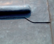 |
| Above: A roll which terminates short of the drip, allowing moisture to penetrate under the lap: the fault is immediately visible from even a cursory inspection of a roof. Below: Underside lead corrosion can occur where lead which has not formed a stable patina is exposed to condensation. | |
 |
|
| Main picture: A valley gutter with lead rolls in each bay, correctly detailed so that the roll terminates neatly at the drip. The section nearest the eaves is often sufficiently narrow not to need a lead roll. | |
LEAD ROLLS
Rolls are commonly used to reduce the width of lead sheets in wide gutters. In effect a roll is a small upstand made of a rounded wooden core: sheets of lead on either side of the core are lapped over this upstand. In a valley gutter, for example, as the gutter rises in steps from the outlet to the back of the valley, the width widens, making the introduction of a roll necessary on the sections furthest from the outlet.
Incorrect roll ends are a common cause of failure in both flat roofing and gutters. A roll end really must finish at the very edge of a drip or step, but very often roll ends are left well short, allowing water to track under the lap, around the end of the roll and into the substructure. Short roll ends are possibly one of the most obvious visible defects to spot on a lead roof.
UNDERSIDE CORROSION
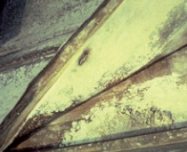
The final area to be considered with regard to common defects in lead installations is a problem that has only recently been properly identified and understood. It is caused by condensation on the underside of the lead sheet where, in the absence of weathering, the lead may not have formed a stable patina, leaving it vulnerable to decay.
One source of condensation is warm moist air from rooms below, such as a kitchen, bathroom or even a heavily used function room, which condenses on the cold underside of the lead if there is no airflow. Another common cause is thermal pumping: if the lead sheet is laid on an unventilated warm roof (with boards laid directly onto insulation sealed from below by a vapour barrier), a rain shower on a warm day will cause the air inside the roof to cool rapidly and contract, sucking in air and water through the laps in the lead above. Once inside, it evaporates in the warmth and condenses when the temperature drops against the cool underside of the lead.
In both cases, in the absence of a stable patina, the water causes the lead to corrode through flaking (much the same as rust on steel) until holes begin to appear in the sheet from below. Dry or wet rot can also be created in the substrate.
Where underside corrosion is identified, the solution typically involves relaying the lead over a new ventilated substrate.
WORKMANSHIP
In summary, lead sheet is no different in many respects to most roofing materials in that it will not work if it is not detailed and fitted correctly.
When working on buildings of architectural or historic significance, many main contractors decide the most cost effective route is to place the whole roofing package in the hands of a general sub contractor. This is often a critical and costly mistake which can lead to an outbreak of dry rot requiring extensive repairs to interior roof structures, and the all too familiar refrain: 'It was only a piece of flashing – I didn’t think I needed a specialist'.
~~~
Recommended Reading
Rolled Lead Sheet – The Complete Manual (Reprinted June 2007), The Lead Sheet Association, Tonbridge, Kent