


Lightning Protection for Historic Buildings
Tim Donlon
 |
||
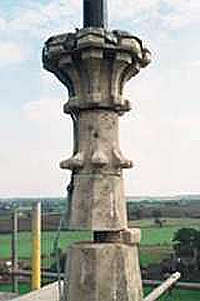
| Figure 1: Eastern Maudit Church, Northamptonshire: An example of the damage caused below a spire-top air terminal by a side flash. Passing through masonry from an internal vane rod, the lightning caused the displacement of solid stonework. |
Lightning, an intensely bright spark or streak of light through the air to ground, has terrified and excited mankind for centuries. Once considered to be in the realm of the gods, it was only in the past 200 years that the theory of lightning has been transferred to the scientific realm, initially through the endeavours of Benjamin Franklin (1751).
There
are different types of lightning: cloud to ground, cloud to cloud and
within a single cloud, not to mention such rare variations as ribbon
and ball lightning. On average a cloud to ground strike would be in
the order of 20,000 amperes with a duration of 0.2 seconds, and at its
peak, the power released can be 100 megawatts per metre.
Although relatively few deaths occur (10 per year in the UK(1)), the possibility of a lightning strike to the structure of a building
such as a small church is much greater, at around 1:500(2) per year in the UK. Mechanical effects and damage are primarily caused
by the explosive expansion of air heated to around 30,000ºC, by the
ignition of dust, and by flying debris. Electrical circuits may also
be damaged by the electro-magnetic field generated.
In a temperate climate lightning is caused by 'frontal' storms which usually occur as a cold front meets warm air, wedging it upwards thousands of feet into the atmosphere. Thunderclouds (cumulonimbus) develop as the moisture condenses and then freezes with altitude. Their development gives rise to charges building up; in general, ice particles in the upper part of the clouds are positively charged, while water droplets lower down contain a negative charge. At the base of the cloud, this negative charge induces a positive charge at 'ground' level. As the cloud continues to grow, the charge increases until the voltage difference between the ground and cloud is so great that the resistance of the air between the two is broken down and a lightning discharge occurs. Recent photographs taken from the space shuttle also show discharges from the top of the thundercloud to the stratosphere; previously such a phenomenon had not been considered.
The actual lightning discharge commences with a stepped downward leader (invisible to the naked eye), negatively charged, searching for an easy path to earth. This induces a positive charge in the form of an upward streamer from a structure or object on the ground such as a building or monument. When the two meet, the potential difference between the cloud and 'ground' is equalised, causing the bright flash known as the 'return stroke'.
The effect of a lightning conductor placed appropriately on any building is to create an 'apparent earth' short circuiting the intense electric field below a thundercloud. This allows positive ions to be transferred through the conductor to the atmosphere, as an upward streamer. At any one time there may be many upward streamers being formed from a building through various parts of the lightning conductor system or other non-conductive parts of the building, and the aim of a lightning conductor designer is to provide suitably placed conductors based on this knowledge.
An upward streamer can be formed by all sorts of objects - blades of grass, trees and manmade structures, notably including ships' masts and rigging where it produces the phenomenon known as 'St Elmo's Fire' after the patron saint of Mediterranean sailors. (3)
The lightning conductor is not an 'attractor' as the movement of positive ions is governed by the prevailing wind conditions. However, it does give the current the easiest path to earth, avoiding the transfer of current through less conductive building materials and the subsequent structural damage this can cause.
The points on a structure most vulnerable will be those points nearest the stepped downward leader on its last step, the length of which is termed the 'striking distance'. This distance is represented in the British Standard 6651:1992 (clause 14.3) by a sphere of radius 60m which, in effect, can be rolled around the plan and elevations of the structure to determine the extent of protection required. Reducing the radius to less than 60m gives greater protection but adds to the cost of the installation.
PRINCIPLES OF PROTECTION
The provision of a system depends on the type of historic building under consideration. British Standard 6651:1992 assesses the 'Need for Protection' against a series of factors concerning the location, use and construction of a structure. This BS provides an indication of the relevant factors only and specific calculations should be carried out if any doubt exists or if the criteria for each index figure are likely to change.
In the past British Standards were based on the installation of a single down conductor to the highest point of a building (British Standard Code of Practice 326:1965). This approach was designed to create a 'Zone of Protection' which was formed by striking a 45º line from the top of the conductor. However, it is now known that this may not be sufficient, as lightning is known to strike the sides of tall structures which should not occur if the 45º Zone of Protection applied to all structures.
Eastern Maudit Church, in Northamptonshire (Figure 1 above) is one example of a church spire having a single down conductor which suffered a 'side flash' through the mortar joints in the solid section of the spire to the metallic vane rod used to compress the tip of the spire. This was in spite of the rod being bonded top and bottom to the down conductor in accordance with British Standard 6651:1992. The lightning flash appears to have travelled through the open and weathered joint, similar to the way water moves through minute fissures via capillary action, and the mechanical force of the strike has blown a section of the spire stonework away.
A further example of this phenomenon is illustrated by the unprotected parapet wall at Lulworth Castle, Dorset which was struck in 1995, the lightning flash having travelled along the bed joint of the parapet, dislodging the copings and splitting the masonry below.
Currently Dr Norman Allen, of UMIST, is researching this phenomenon, which is currently specifically disregarded in the British Standard 6651:1992 (clause 18.2.2).
The latest standard recommends that a series of down conductors is installed to protect the whole building, with towers and spires having a minimum of two down conductors placed diametrically opposite each other and horizontal conductors (coronas) vertically at 20m centres. The remainder of the building should be protected with a series of conductors interconnected to form a 20m x 10m 'Air Termination' grid, using where possible elements of the structure, such as metallic gutters, lead roofs, and so on. Also prominent features such as pinnacles, crosses, and flêches should have additional air terminals, as they will form upward streamers under the right conditions.
The air termination must then be connected to ground with a series of down conductors spaced around the perimeter of the buildings, one for every 20m of perimeter (for structures more than 20m high this is decreased to 10m spaces).
In order to provide adequate protection in accordance with BS6651:1992 the bonding to electrical and other services, and all extraneous metal such as flagpoles, bell frames and flues, is essential, to equalise the potential difference between those items and the lightning conductor during a strike. This is often ignored in the interest of expediency and cost.
Once installed, down conductors and air terminations must be adequately earthed to ground with a series of electrodes, which may take the form of either driven rods, plates or mats made from copper. In some cases a drilled bore hole filled with Bentonite is required where the underlying strata is rock, and there are special systems of overlaying conductor tapes. The resistance to earth of each electrode must not exceed ten times the total number of interconnected electrodes on a system. (For example, for ten electrodes each one should have a resistance of less than 100 ohms. This will give an overall resistance to earth of less than 10 ohms.)
THE INSTALLATION
Historic buildings were not constructed with lightning protection in mind, and the appearance of a new system of air terminals and conductors can appear intrusive.
The choice of material is critical in reducing the usual impact of the system. The cheapest material to specify would be bare aluminium and PVC clips. These are quite adequate for the purposes of protection but are ugly and detract from the overall appearance of the structure. Perhaps the most suitable material for a sympathetic installation is 8mm solid circular copper conductor with heavy duty cast cable saddles. Alternately, the conductor can be sheathed with a suitably coloured PVC to blend with its surroundings. In this way the conductor appears part of the building rather than contrasting with it.
 |
||
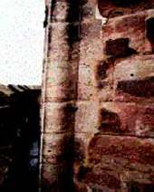
| Figure 2: All Saints Church, Hereford: a good example of what can be achieved. This 8mm bare copper down conductor with heavy duty cable saddles has been positioned behind the roll and in its shadow line so that it is almost invisible from all but one aspect. |
The positioning of the conductors is equally crucial to the overall appearance of the building. While strict adherence to the British Standard will produce a functional lightning conductor system, by placing the conductors behind buttresses and out of sight lines, the whole aspect of the building remains undamaged. This may entail interpretation of the design criteria of BS6651:1992. However, the Standard makes allowance for these situations in its guidance notes and foreword.
Typically, in a well designed installation, the air termination is hidden behind parapet walls with short finials, and down conductors are placed behind pinnacles and in returns of buttresses or other key features. They should always be straightened and installed with a string line, following the lines of the building. On rubble or pitch faced stonework they should not be dressed into each crack and contour of the stone as the conductor then looks poorly installed in profile.
It is always prudent to use the features of the building to mask the visual effects of a conductor. For instance, it is prudent to shadow a strong feature on a spire or tower, following a stone quoin or roll as the human eye will focus on the more prominent feature and disregard a conductor placed next to it (Figure 2).
The down conductor must have a facility for testing the earth electrode below: a purpose made test clamp should be positioned in each down conductor at a uniform height to allow access for testing but not to encourage tampering. Electrodes are generally driven into the ground in multiples of 1.2m lengths; it is therefore essential to check for underground hazards, such as services and archaeological artefacts, before deciding on their positions.
Once installed, the lightning conductor system should be commissioned and maintained with an inspection and a test of each electrode carried out by an approved contractor annually and immediately following a lightning strike. There is little sense in having a system carefully designed and installed which is not adequately maintained.
The installation of a lightning conductor to an historic building also requires the selection of a qualified contractor, who is capable of understanding the importance and delicacy of the various features and the nature of the construction to which the system is being installed. The National Federation of Master Steeplejacks and Lightning Conductor Engineers aims to provide a standard of quality and service through its members who have achieved the necessary level of competence in all aspects of their work, emphasising quality of training and professionalism combined with 'Safety through Training'. More damage may occur to the fabric of the structure through selecting the contractor on price alone than may be caused by a lightning strike, so all factors available should be considered before deciding to proceed.
THE IMPORTANCE OF ADEQUATE PROTECTION
The provision of a lightning conductor system will not prevent the occurrence of a lightning strike. The purpose of the installation is to direct the current discharged from the strike to earth safely, protecting the structure and its occupants from the effects of the strike.
At one church where there was a lightning conductor system (albeit not up to current standards) the bell ringers of Yoxall decided to continue to ring during a thunderstorm. They later described how 'the air was full of bright butterflies, the carpet was swimming with a haze of electric blue cobwebs and the pins and needles lasted for hours'. Their decision to stay turned out to be a wise choice since 'had we decided to call it a night, we would most certainly have been below the falling pinnacle' (The Ringing World, no 4376, March 10th, 1995).
~~~
Notes
(1) Smith, Principles of Applied Climatology (details below)
(2) British Standard 6651:1992 - Protection of Structures against
Lightning (details below)
(3) Golde, Lightning Protection (details below)
Recommended Reading
- Keith Smith, Principles of Applied Climatology, McGraw Hill, London, 1975
- Norman L Allen, The Protection of Churches Against Lightning, Council for Care of Churches, 1988
- RH Golde, Lightning Protection, Edward Arnold,
London, 1973
- Peter E Viemeister, The Lightning Book, MIT Press, Cambridge, Massachusetts, 1973
- British Standard 6651:1992 - Protection of Structures against Lightning, British Standards Institute, 1992