


New Wires for Old
Robin Wright
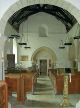
Despite the obvious importance of maintaining and updating electrical wiring, faulty wiring remains one of the most common causes of fire in historic buildings. A surprisingly large number of buildings still retain wiring installed in the mid 19th century and, in some cases, the earliest forms of wiring are still in use, presenting a constant threat not only to the building and its contents, but also its occupants. It is an unseen problem, and often not even the owners are aware of the situation. In churches, which are subject to regular architectural quinquennial surveys but not always to electrical quinquennial surveys, the risk may be understood but may not be dealt with due to a lack of funds. The situation is not helped by English Heritage and the Heritage Lottery rarely providing funds for the replacement of old, dangerous electrical wiring unless it can be claimed as part of the building work. However, wiring within a listed historic building is now not subject to VAT providing that listed building consent has been granted for the work.
ASSESSING THE PROBLEM
The Electrical Regulations, BS 7671: 2001 state that electrical wiring should be regularly tested. In Guidance Notes Number 3, a supplement of BS 7671:2001, a table gives recommended frequency of testing for various buildings. In ecclesiastical and secular historic buildings it is generally accepted that if a building has been rewired, the first periodic test should be after five years; for wiring older than five years, periodic tests should be carried out every 2½ years. In practice, however, the periodic testing of electrical wiring rarely takes place, as it is considered to be a very costly and disruptive exercise. As a result, the scale of the threat to historic buildings has never been fully quantified.
The wiring in historic buildings generally falls into one of three categories:
1. Very old wiring predominates with vulcanised rubber (VIR) cables. These are often run within steel conduits, or are protected by a lead sheath and installed within the building fabric. There may also be some mineral insulated copper (MICC) sheathed cables.
2. Wiring is a mixture between VIR cables, poly-vinyl chloride (PVC) twin-and-earth cables and MICC cables with or without a plastic sheath; all of varying ages.
3. All wiring is of new MICC/PVC cable or new PVC twin-and-earth cable.
Where wiring falls in the first category, the existing wiring in VIR cables and lead sheathed VIR cables will have long passed the end of its productive life. It would not be a good idea to carry out any electrical testing of the circuits, as the rubber sheath would now be so old and perished that harm would be done to the installation, thus leaving the installation in a more dangerous state than existed before the insulation resistance tests were undertaken.
 |
||
| Statistics collated by the Ecclesiastical Insurance Group indicate that electrical faults in churches cost £5 million each year. In terms of historic value the loss is incalculable. |
With the second category of wiring, a careful survey of the existing electrical installation should be carried out and certain parts of the electrical installation tested to establish which parts of the wiring may be reused and which parts must be replaced.
With the third category of wiring, the electrical installation will have to be tested in accordance with BS 7671: 2001, Part 7, Chapter 73, Periodic Inspection and Testing. Chapter 73 describes the procedure and method of testing the electrical installation, and gives full details of each test to be performed. Further details can be obtained from Guidance Notes Number 3. The periodic test report will show the condition of the electrical installation at the time at which the tests took place, and will list the rectification work required for the entire installation to comply with current regulations.
In historic buildings, where lighting points and switches are to be kept in their original locations and the old VIR cables are found to have been run in conduits, new PVC single cables could be run within the existing conduits to the existing points, thus saving a lot of builders’ work, re-plastering and redecorations. Care must be taken to ensure that each circuit has its own live, neutral and earth conductor, as the existing steel conduit cannot be guaranteed to be continuous. The steel conduit has to be earth-bonded to make the system complete.
The new PVC cables should have a ‘low smoke and fume’ (LSF) sheath to ensure that the cables are not liable, like ordinary PVC cables, to produce corrosive halogens and copious smoke in the event of a fire, which is not only a life-safety issue but also reduces the smoke damage to the contents of an historic building.
Old MICC cables do not have a plastic sheath, but electrical tests could be safely carried out. It is often possible to re-use old MICC cables, providing that cable faults are not shown during the electrical tests and that voltdrop and earth-loop impedance calculations are carried out to ensure that the existing MICC cables still comply with BS 7671:2001. Even if the insulation resistance of the cables failed the tests, all might not be lost; frequently it is the electrical equipment connected to the cable which is at fault and not the actual cable.
Once the electrical equipment has been disconnected, the cables must be retested and even if the cables fail the insulation resistance tests again, the ends of the cables could be re-terminated; this nearly always solves the problem.
In some bare-sheathed MICC electrical installations, failure to pass the insulation resistance tests is usually caused by a hole in the sheath of the cable. This occurs where bare-sheath MICC cables have been installed in damp locations, particularly where lime mortar has been used, as the water and lime combine to create an electrolytic action with the bare copper. A similar electrolytic action may also have been caused by installing bare-sheath MICC cables on new oak. The reaction causes the copper to be eaten away, making a hole in the side of the cable and letting in water, causing a short circuit between live, neutral and earth. Often the only sign that this has occurred is the appearance of green verdigris on the bare copper sheath. In this instance, the only solution is to replace the section of cable affected.
PVC twin-and-earth cables are not generally recommended for use in historic buildings, as these cables are physically weak and can be abraded when being drawn into the building or by building movement. Furthermore, vermin often attack the PVC insulation, and this material can also become degraded and brittle under adverse environmental conditions and ultra-violet light.
On occasions when, due to cost restraints, some PVC twin-and-earth cables are used, they should be mechanically protected to prevent damage and vermin attack. The protection can be in the form of steel conduit or heavy grade, high impact plastic conduit. The PVC twinand- earth cables should have a low-smoke insulation.
Care must be taken when re-using existing PVC twin-and-earth cables, as the early versions had a 1.0 sq mm earth conductor. The small cross-sectional area of the earth conductor may not comply with the earth-loop impedance requirements of BS 7671:2001, depending upon the length of the cable.
NEW INSTALLATIONS
Having decided if parts of the electrical installation can be re-used or whether the electrical installation needs to be replaced in its entirety, careful design of the new electrical installation can take place.
The designer should always allow for future expansion, incorporating slightly larger cables, trunking and conduits so that additions may be made without having to reopen floors and damage decorations.
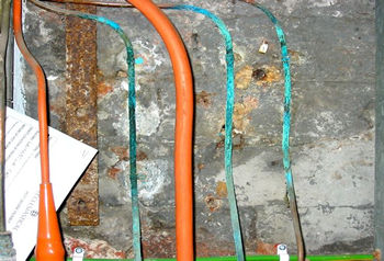 |
||
| Clipping bare-sheathed MICC cables to a damp wall can result in the formation of verdigris and cause the cables to deteriorate. | ||
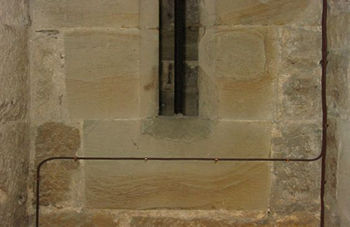 |
||
| This MICC/PVC cable runs across the surface unnecessarily and is fixed made into the stone itself, rather than into the mortar joints. |
To minimise visual impact, as much of the electrical installation as possible should be consigned to non-sensitive areas such as cellars, roof spaces, risers through the building, ventilation-voids, unused chimneys and floor-voids. Where this is not possible, problems may be resolved by various methods of concealment and disguise, and careful selections of materials and finishes. Each building and situation should be treated on its own merits.
It is most essential that the client and architect/surveyor decide upon the type of electrical equipment and locations before the new electrical installation can be engineered. If the historic building is very large, requiring very long cable runs, the success of the design will hinge on its volt-drop characteristics. Most of the volt-drop has to be taken up in the sub-main cables running between the electrical mains intake switchgear and the local distribution boards to avoid the circuit cables from the local distribution board to the lighting and power points becoming so large that they are difficult to terminate into the electrical accessories.
There are usually two types of cables used for sub-main cables; MICC/LSF (mineral insulated with an LSF sheath) and PVC/SWA/ LSF cables (poly-vinyl chloride, steel wire armour, low smoke and fume sheath). The MICC/LSF cable is rigid and is only suitable for certain locations, whereas the PVC/SWA/LSF cable is very flexible and can be more easily woven around the building.
The circuit cables are usually MICC/LSF cables and should not be less than 1.5 sq mm in cross-sectional area. A standard range of sheath colours is readily available off the shelf, in reasonable lengths of 100 metres; in orange, black, light brown, dark brown, stone, grey, blue, yellow, red and white. Where a suitable colour of sheath does not exist, the cables should be painted to match the surface upon which they are being run. Of course, the cable clips and shrouds should be the same colour as the cable.
When fixing cables, the surface of historic stone or brickwork must not be damaged in any way. Where running cables across a brick or stone surface is unavoidable, the cable should be fixed into the mortar joints between the stones or bricks using brass fixing screws so that they can be removed at a later date without damage to the historic fabric. Where the mortar joints are friable, the existing mortar joint should be raked out and refilled with a mortar composition specified by the architect or surveyor.
When drilling any holes for fixing the wiring and electrical equipment or for passing cables through structures, the electrical contractor should use an electric drill with an efficient vacuum cleaner attachment to ensure that all the dust is sucked away and does not settle within the room. Cartridge fixing tools should not be used.
Where the cables must pass through the walls, holes should be made using a diamond core drill (again with a vacuum attachment to remove the dust) so that a hole is neatly made with the minimum of damage to the masonry. Where cables pass from one fire compartment to another, the walls, ceiling or floor through which they pass must be effectively firestopped with a suitable fire barrier to prevent the passage of smoke and flames as well as rodents.
Where cables are chased into the plaster walls, they should be carefully and neatly made by hand and run within 20mm round plastic conduits so that rewiring can take place at a later date without the need to re-cut chases in the walls, thus preventing further damage to the decorations in the future.
The cables should have cable-markers at each point at which they are terminated within the switchgear, luminaires, lighting switches, socket outlets and all electrical equipment, including accessories and junction boxes. They should also have cable-markers at every three metres within trunking, indicating the circuit number, distribution board number and the colour of the phase.
Cables within roof-voids should be run on galvanized cable trays above the thermal insulation. When cables pass through the thermal insulation, they must be at right angles so that the cables are in contact with the smallest possible amount of thermal insulation to minimise the heating effect of the thermal insulation on the cable.
Where cables pass through floor joists, these joists shall be drilled in the centre rather than slotted. All cutting of joists must be kept to an absolute minimum. If notching of the joists cannot be avoided, the cables must be covered with 3 mm steel plates to prevent penetration by nails and screws. Old notches should be used where possible. The approval of the architect and structural engineer must be obtained before any new notches are cut in the floor joists. Further details regarding chasing of walls and running cables within floor and ceiling voids can be obtained from the IEE On-Site Guide (to BS 7671:2001 and the amendments).
The IEE Amendment No 2: AMD 14905 to BS 7671:2001 details the new colours of cable conductors to be used.
Electrical installations commencing on site after 31 March 2004 and before April 2006 may be installed in accordance with Amendment No 2 or Amendment No 1 – that is to say, the new harmonized colours/marking or the old colours may be used, but not both.
Installations commencing on site after 31 March 2006 are required to use the new harmonized colours or marking.
From now until 31 March 2006, the new cable colours may be used to extend an existing electrical installation providing that a warning notice is attached to the particular distribution board stating 'CAUTION. This installation has wiring colours of two versions of BS 7671. Great care should be taken before undertaking extension, alteration or repair that all conductors are correctly identified'.
As many extensions, repairs and alterations of the electrical installations in historic properties are carried out over a number of years, all new work should be carried out using the new cable conductor colours. The new cable conductor colours are as follows:
| TYPE OF CIRCUIT | OLD COLOUR | NEW COLOUR |
| SINGLE PHASE CIRCUITS | ||
L Phase conductor (live) N Neutral conductor E Earth conductor |
Red Black Yellow/Green |
Brown Blue Yellow/Green |
| THREE-PHASE CIRCUITS | ||
L1 Phase 1 conductor L2 Phase 2 conductor L3 Phase 3 conductor N Neutral conductor E Earth conductor |
Red Yellow Blue Black Yellow/Green |
Brown Black Grey Blue Yellow/Green |
The art of a good electrical installation in an historic building is to ensure it fulfils all present requirements and allows for expansion, but is unobtrusive with cables, accessories and switchgear out of sight. By using the right cables and methods of installation and concealment to suit the building and maintain its historical integrity, the result will last for many years to come.
~~~
Recommended Reading
-
Technical pamphlet 9 Electrical installations, SPAB Lighting and Wiring of Churches, CIO Publishing, Dean’s Yard, London SW1 3NZ
-
BS 7671:2001*, British Standards Institute Guidance Notes Number 3, British Standards Institute
-
IEE On-Site Guide (WR241), Institution of Electrical Engineers
-
Roger W Moss, Lighting for Historic Buildings, The Preservation Press