


Measuring in 3D
New approaches to digital measuring for stained glass at the York Glaziers Trust
Nick Teed and Zoe Harrigan
 |
|
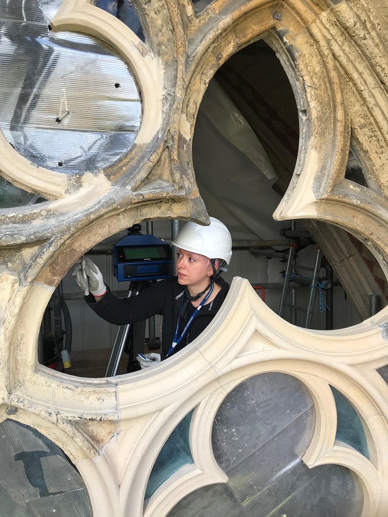
| Conservator Zoe Harrigan measuring the profiles of a window (CHn5) in the Chapter House Vestibule of York Minster in 2021 (All photos: York Glaziers Trust) |
The taking of accurate dimensions and templates of stone or timber window openings has long been one of the most critical aspects of a successful stained glass project, whether a window is to be removed for studio conservation or a new commission is to be created.
It is essential that any window forming the weather shield for a building is well fitting, secure and weather-proof. With the help of a good template, a previously ill-fitting window can be improved with simple remedial measures such as the addition of extra lead at the perimeters.
Environmental protective glazing (EPG) is also frequently used to prolong the life of historic stained glass exposed to decades or even centuries of wetting and drying cycles, which promote deterioration of both glass and painted detail. The development of these complex glazing systems relies on an array of accurate dimensions to aid in the design of an installation appropriate to the profiles of a specific window structure.
With this in mind, the team at the York Glaziers Trust (YGT) was keen to discover whether new technologies were available to complement or even replace traditional methods of creating paper or card templates of complex window shapes, while also improving on the accuracy and speed of execution.
Traditional Technologies
For many years, staff training at YGT has included the best traditional methods for plotting the glazing plane in often complex window openings. These rely on accurate readings of tape measures which take account of glazing bar positions, followed by the preparation of carefully cut out paper templates for architectural canopies or window traceries.
For the glazier, these measurements are most useful at the visible stone edge between the mullions or tracery openings, often referred to as sight size. With this information, the glazier can determine precisely how much lead should be allowed to set into the glazing groove and how much should be visible outside the groove (normally a case of half the perimeter lead showing and half within the groove).
In recent years YGTs team has started to use digital laser measuring tools, which have proved to be affordable, accurate and convenient for straight dimensions. However, paper or card templates continued to be essential for shaped openings. Following a number of projects that contained significant quantities of shaped traceries (for example, the conservation of the Great East Window at York Minster, and the East Window of Lincoln College Chapel, Oxford) the team began to explore whether other options were available.
This research was greatly facilitated by a new initiative supported by the York Minster Fund, securing the technical expertise of engineer Laura Cotter, who has worked with both the YGT and the York Minster stone yard in investigating new technologies of mutual interest and benefit.
The glaziers and masons have frequently worked in close collaboration on Minster projects, ensuring that maximum advantage is taken of high level access whenever costly scaffold structures are in place. The research work conducted by Laura pointed to a number of companies which were able to demonstrate different approaches to how the measuring requirements of historic glass and stone could be met in the digital realm.
Laser Scanning
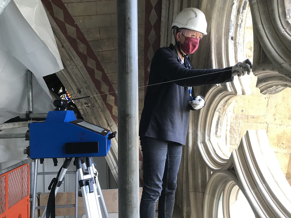
A portable coordinate measuring machine, the Prodim Proliner, being used by Zoe Harrigan on window CHn5: above, the angle of the cable and distance to the steel pointer are accurately measured by the device to plot the position of each point in 3D.
Our first investigations looked into the capabilities of laser scanning and photogrammetric 3D scanning. We were able to arrange several on-site demonstrations of a range of different scanners to look at the possibilities in practice.
We learned how hand-held portable units, based on photogrammetric scanning technology, could produce very interesting and accurately-rendered 3D models, with the possibility of gaining dimensions from the resulting files.
A demonstration of a laser tracking system showed us the extraordinary precision that could be achieved in the gathering of dimension data from 3D files.
Despite being hugely impressed by what the 3D scanning technologies could achieve, we realised that our own needs were far simpler than the complex capabilities of these systems.
We were looking for a user-friendly system that could accurately measure the spaces and capture the shapes of window traceries, and create a simple and very accurate line drawing in two dimensions. We actually had little need to create a huge point cloud digital file, or an accurately rendered 3D model, although these impressive tools are excellent for documenting historic material for use in interpretation. Our next demonstration was of a quite different piece of technology, a coordinate measuring machine called a Proliner.
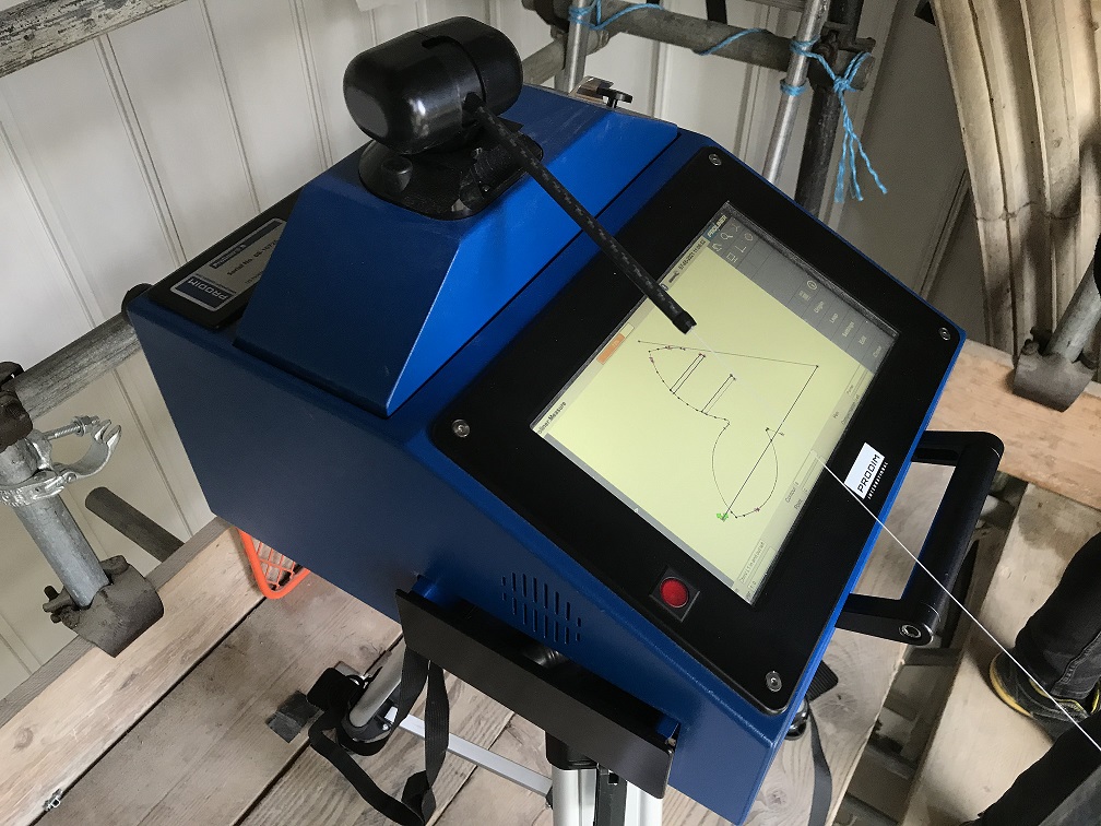
The form takes shape on the Proliner display screen.
CMM Technology
A coordinate measuring machine (CMM) is a device that plots the geometry of an object from a series of three-dimensional coordinates. These are measured using a probe connected to the machine (directly or indirectly) while its tip touches one of the series of points to be measured.
In some cases the probe operates on rails in two or three axes, with distance to the point measured in each axis. In others the probe is held on an articulated arm, with accurate angular measurements calculating the coordinates of each point in 3D.
The Proliner is manufactured by the Dutch company Prodim. Like other forms of CMM it works by taking individual measurements in 3D space to create an accurate 1:1 drawing of any shape, but in this case the steel probe or pointer is on the end of a retractable steel cable that is calibrated to measure objects and structures up to five metres away, in all directions.
The cable is calibrated to within a 0.5mm margin of accuracy. The measuring unit can be used with a dedicated tripod in order to fine-tune the starting position of any new project. By keeping the unit in a fixed position, the measuring wire can then be extended and the pointer set to the object in this case the stone window surround.
 |
|
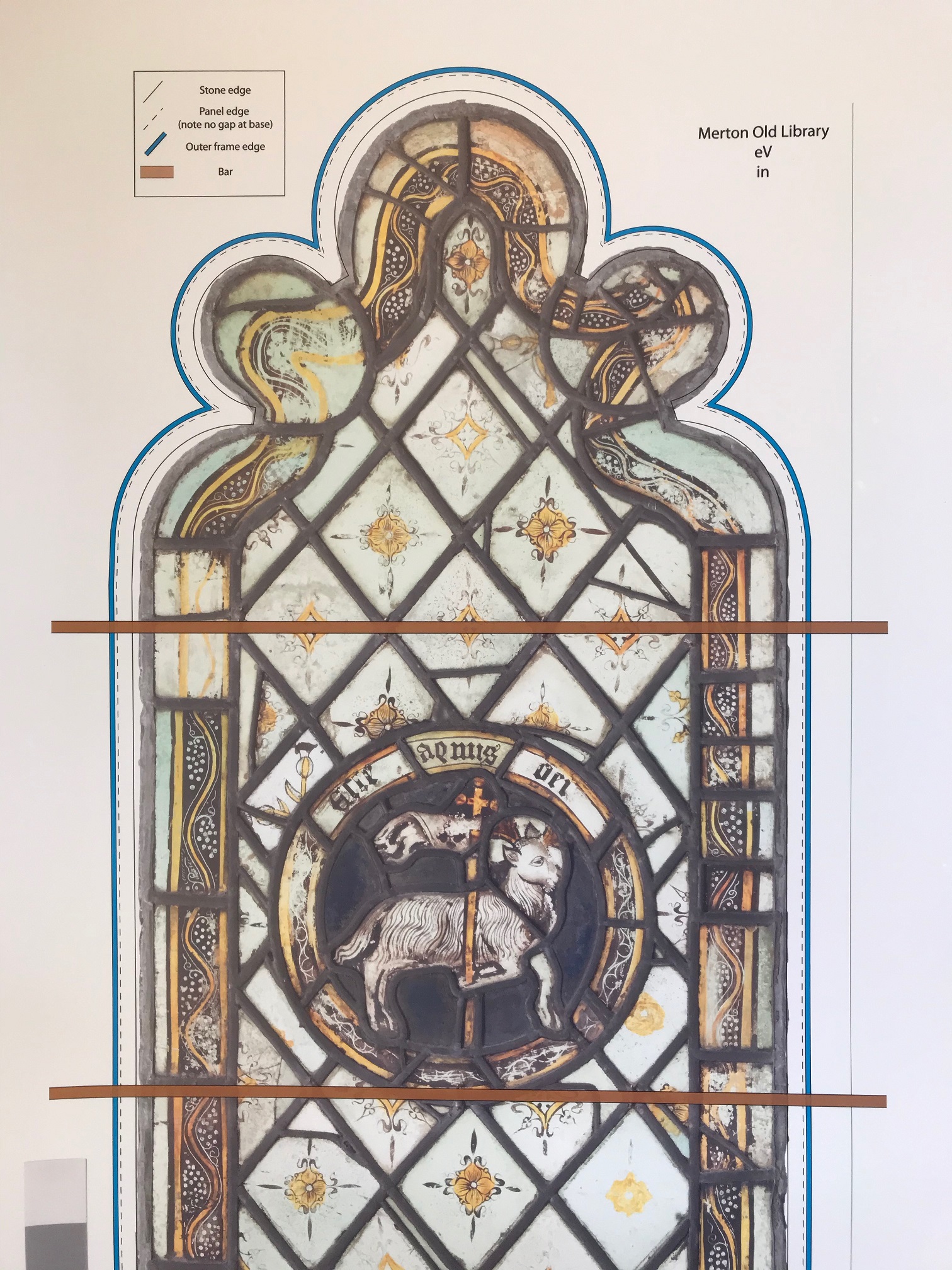
| A CMM drawing worked up in Adobe Illustrator shows the proposed panel position and the frame position according to the stone profile of a window in Merton College Old Library, Oxford. |
The dimension is then taken by pressing a button on a dedicated remote control device or in an app on a mobile phone, and the operator can take as many measurements as necessary to make each template drawing. As the device measures in 3D space, not only can the stone surround be measured but so too can other features on different planes, such as the exterior stone profile (if it differs from the interior) and any metal bars connected to the stonework.
As the device contains a self-calibrating inclinometer, each template drawing can include a spirit level position to ensure that panels and supporting bars are set accordingly. Once a drawing is complete, the file is saved and the unit can be moved to the next window. Very large shapes, which cannot be measured from a particular position due to obstructions such as scaffolding, can be measured in stages.
To ensure the templates continuity, each stage (or leap) is linked together by including a fixed object which can be measured from each tripod position. The files created by CMM are simple linear drawings, which can then be exported to CAD or Adobe Illustrator software for further development or use, or they can be exported as PDF files for stand-alone printing.
During the demonstration by Prodim, we were able to quickly and accurately record the shapes and dimensions of several complex tracery sections of the stone surround of a Chapter House Vestibule window which was undergoing conservation at that time.
We were immediately able to compare the results with our traditional paper templates, and were very satisfied that the improved levels of accuracy claimed for the unit were absolutely justified. Since our decision to invest in a Proliner device we have continued to expand on its use and found it to be a tool which provides a multitude of functions from the original measurement file.
Using the touchscreen on the unit a template drawing can be adjusted to include offsets for frame sizes, glass cutline sizes, and full leaded panel sizes. This allows one drawing to serve a number of purposes, saving time and material costs in comparison to making several hand-drawn templates.
Our own preference is to then export the measurement file into Adobe Illustrator where it becomes the starting point for drawing a protective glazing cutline or a frame pattern, which can then be printed 1:1 on a large format printer. In this software, images of the stained glass panels can be combined with the CMM data at full size to use as a guide during conservation, effectively taking the place of a panel rubbing.
This is particularly useful when additional leads may be required to bring a loosefitting panel up to size and shape. The simultaneous use of these different elements within the same drawing allows us to streamline our working processes. It ensures that the design of the protective glazing system fully matches the stained glass on which it is based, and that both will fit extremely accurately within the masonry of the window opening.
Conclusion
There are a number of ways in which modern technologies can assist in gathering accurate dimensions for conservation work on historic buildings. Many of these technical instruments require a measuring or data gathering stage, followed by an in-depth processing of file data in dedicated software.
This is particularly the case with 3D scanning technologies, which can create extremely large files and require a detailed knowledge of the software applications. Our own research confirmed that 3D scanning captures a great deal of visual data on window frame shape and appearance, but our specific requirement was a focus on the recording of accurate size and shape above the need for visual 3D interpretation.
Furthermore, we had no need to gather information from a remote distance since template making is usually carried out from a scaffold. This simpler set of requirements determined our decision to invest in the Proliner, which is first and foremost a measuring tool.
The small file sizes, ease of use of the device, and the accuracy and versatility of the resulting files make this a valuable asset to our working practices within the field of stained glass conservation.
Having accurate templates of the stonework in a digital format also means that we can preserve this information for future generations of conservators, while minimising the need to store significant quantities of paper templates and drawings.