


The Ins and Outs of Weathering to Walls
Fred Coote
Lead sheet is widely used for flashings and weatherings to walls and abutments. In fact, about 75 per cent of the lead sheet used annually in the United Kingdom for building purposes is employed at abutments, cornice projections and parapet wall cappings. When it comes to the conservation and repair of historic buildings, the roof is rightly given top priority as any work on other parts of the building could be quickly damaged by water penetration from above. However, the roofing system or material may not always be the cause of leakage. The origins of many of these failures can be traced to defects and faults in abutment walls and associated weatherings, including porous brick or stonework, the lack of a damp proof course (DPC), the breakdown of pointing where flashings are turned into brickwork or masonry, and the failure of the lead flashings or weatherings themselves.
The purpose of an abutment flashing or weathering is to protect the junction between the wall and an adjacent surface, for example, the roof covering. It does not prevent water penetration down through the wall. A DPC membrane or a course of high density masonry is usually included for this purpose. Slates and plain tiles are usually detailed with soakers and step flashings where they abut the wall. Profiled interlocking tiles should be covered with step and covered flashings and flat tiles should be weathered with secret gutters. The perimeter of flat roofs, whatever the material, should be weathered with cover flashings. Pitched roofs close to the underside of coping stones are usually detailed with soakers and mortar fillets. To improve this detail it is possible to fit soakers without a fillet or cover flashing providing that the soaker is built in under the coping stone.
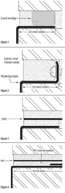 |
Flashings at abutments should be turned into the wall at least 25mm and be secured with wedges at not more than 450mm centres (see Figure 1). Lead flashings should be fitted in lengths not exceeding 1.5m with 100mm end to end laps. It has been common practice in the past to fold back the edge of the lead tucked into the wall. This is incorrect as it prevents adequate adhesion of the pointing material to the soffit of the joint or groove in the masonry wall.
When fixing into a very thin mortar joint (say 4-8mm) in stonework it is not usually possible to secure the flashings with wedges, so a groove must be cut, 12mm wide and 25mm deep, into which the lead can be dressed and wedged. Problems may also occur when flashing pieces are secured by lead wedges in wide joints in stonework. When subjected to wind vibration or changes in temperature, the wedges often fail to hold the flashings, and the pointing cracks away from the top joint, allowing water to penetrate.
Figure 2 shows the recommended method for fixing lead flashings into joints over 18mm wide. Each length is turned up the back of the chase, or 'raggle', and fixed by stainless steel screws and washers at about 450mm centres. To ensure efficient weathering it is essential that pointing is carried out correctly and one successful method - especially on historic buildings with extra-wide mortar joints - is to introduce masking tape between the mortar and the lead. By using the correct mortar and thoroughly wetting the masonry a good adhesion between them can be achieved and the tape trimmed-off flush after the mortar has set. This permits the lead to expand along its length independent of the mortar. Experience has shown that water does not penetrate through the hair's breadth joint between the tape and the lead because of the barrier caused by the turn-up. This practice is not suitable where there is no lead upstand.
For joints between 10 and 20mm wide it is also possible to point with an appropriate mastic sealant instead of mortar. The mastic sealant will adhere to the masonry and to the lead and will be able to accommodate the differences in expansion without cracking. Here, the masking tape will not be needed as the sealant will absorb the thermal movement between the lead and the masonry. Whatever method is used, the pointing material must be tightly compacted and bonded to all surfaces.
In more exposed situations where rainwater is absorbed or driven by the wind into the wall, water could percolate beyond the 25mm turn-in and dampen the structure below. This will also happen in extreme exposures even if the masonry is itself impervious, because the joints will almost certainly be somewhat porous and water will penetrate down through the vertical joints. It will then be necessary to fit a DPC or clad the parapet wall. Lead sheet is an ideal material for use as a damp proof course in solid masonry walls. Providing that it is fitted correctly it will outlast most other DPC materials. It may be bossed or welded and is therefore particularly suitable for prefabricating all types of damp proof courses especially where it is otherwise difficult to provide a continuous membrane. If it is not possible to wedge the flashing under the DPC then it should be turned over the top of the masonry by 50mm and finished with a welted edge.
The DPC is then bedded down on to the flashing (see Figures 3 and 4 ). All lead sheet built into mortar more than 50mm from the outer face of the stone or brick should be coated on both sides with a cold application bitumastic paint. All DPCs should finish flush with the outer face of the wall.
 |
If a wall is porous and it is not possible to fit a DPC then it will be necessary to clad the face of the wall. This can be done with lead sheet, which should be secured with two rows of copper or stainless steel clout nails across the head at 75mm centres in a staggered pattern. The fixings should then be covered with a separate cover flashing.
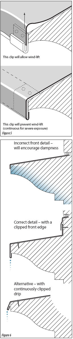
It may also be advisable to fit a lead capping to the top of the wall. This should be detailed in lengths not exceeding 1.5m depending upon the width of the wall and the thickness of lead sheet used. It should overlap any side flashings or cladding by at least 75mm. For long walls, each length should be jointed with welted joints with clips engaged into the welts. For party walls and parapets which follow the pitch of the roof, each length should be secured at the top end by two rows of fixings and overlapped by at least 150mm by the next section above. In both cases the side edges should turn down the faces by at least 75mm and finish with a welted edge with clips tucked in to secure against wind uplift. Similar details apply to the weathering to cornices and ledges where stone is often worn down and may require the protection of a lead covering. It is very important to detail the front edge correctly so that water is shed clear of the stone (Figures 5 and 6 ). Wherever lead is laid on stone or concrete, a layer of building paper to BS1521 Class A, should be placed under the lead sheet to allow thermal movement to take place and to protect against corrosion.
RESISTING WIND LIFT
Although lead is among the heaviest of metals it must still be secured against wind uplift. The abutment flashing or weathering remains at the mercy of high winds if the designer or contractor is not aware of a few simple precautions at the time of application. Upon refurbishment of an old building, the thickness or code of lead sheet specified is often lighter than previously used, and it is not always appreciated that stronger fixings are required (Figures 5 and 6 ).
In moderate to severe exposure, clips made from lead are not recommended, even with a heavy code of lead sheet. Clips should be cut from stainless steel strip not less than 50mm wide and 0.38mm thick. Alternatively, clips may be formed from copper sheet of quarter hard temper not less than 0.6mm thick. Clips should be positioned at between 300mm and 500mm centres depending upon the degree of exposure to wind. This is determined not only by reference to wind load and speed factors found in British Standard (BS) Code of Practice (CP) 3, Chapter 3, Part 2, Wind loads and BS5534 Code of practice for slating and tiling, but also by taking into account the immediate orientation and location of the building. For instance, if the building itself is surrounded by other buildings or trees, it could well be regarded as sheltered; but if it were on top of a hill in open country, or overlooking the sea, it would be considered to be in a severely exposed position. The position of the fixing point for the clip must also be considered when providing clips to the free edges of lead flashings. The holding power of a lead clip with a fixing point (fulcrum) 150mm or more from the free edge is virtually nil. If the fulcrum point is between 50mm and 75mm from the edge, less leverage is available and the wind cannot lift the edge of the lead flashing.
Where it is not possible to obtain a close fixing point for the clip, a thicker gauge material should be used. Each clip should be turned at least 25mm over the edge of the flashing. In very severe exposures it may be necessary to use a continuous fixing clip engaged into a welted edge. Providing that the correct code or thickness is used, and the lead sheet is fitted correctly, it should give a service life in excess of one hundred years. Some of the most common faults and issues have been covered in this article. For further advice and information please contact the Lead Sheet Association.
The Lead Sheet Association is a trade association providing technical advice, publications and training for the correct design, specification and application of rolled lead sheet in construction.