


Repair and Conservation of Reinforced Concrete
David Farrell and Kevin Davies
 |
|
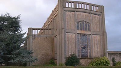
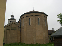
| Figure 1 St Andrew’s, Felixstowe, by Hilda Mason and Raymond Erith (1930-1) |
Reinforced concrete (RC), first used in the construction industry in the late 19th century, became popular for the construction of churches early in the following century, and many early examples of reinforced concrete churches are still in use today. The system offered the advantage that much greater spans could be achieved economically, thus facilitating much greater flexibility in architectural design. Also, compared to stone or brick, RC allowed the walls and general support structure to be reduced in thickness.
Concrete alone, which has been used for centuries, is strong in compression but relatively weak in tension. Steel reinforcement, which may consist of bars, rods, meshes and wires, is designed to overcome this limitation. Bonding and mechanical attachment of the reinforcements to the concrete is essential for the two materials to combine to form a high strength material. In the early 20th century the bars were hooked and twisted together to improve the attachment to the concrete. In later years these were replaced by hot-rolled ribbed and deformed carbon steel bars, and a mesh reinforcement was introduced, made of mats of welded small diameter bars.
As the coefficient of expansion of steel and concrete is similar, the two materials may be effectively combined without suffering thermal-mechanical effects. The reinforcement is used principally to increase the strength of concrete, but it also serves to limit crack propagation when the reinforced concrete is placed in tension.
Many of the early reinforced concrete churches now require repair and conservation. Unlike stone, the repair and conservation of historically important concrete is still in its infancy, although English Heritage is currently conducting a number of trials in this area. Repair of RC normally encompasses traditional patch repairs and replacement but it can also include more modern approaches, such as the use of cathodic protection, re-alkalisation, chloride removal, corrosion inhibitors and anti-carbonation coatings. This article outlines the traditional methods of repair using conventional materials and also illustrates where more modern repair materials and techniques have been used to effect repair. (A further article on cathodic protection by David Farrell, Kevin Davies and Iain McCaig was published in The Building Conservation Directory in 2001 and is available HERE.)
DETERIORATION MECHANISMS
The majority of damage that occurs to RC structures is due to corrosion of the embedded metal reinforcements. Reinforcing steel, being the most common metal used in concrete, is usually protected from corrosion for many years in good-quality high-alkalinity concrete.
 |
|
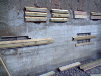
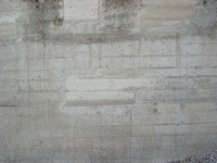
| Figures 2 & 3 Breakout and repairs using formwork (Photo: Francis Doherty) and (below) the finished work | |
 |
Steel immersed in an alkaline solution forms a very stable film of iron oxide on its surface, thereby mitigating any further corrosion. The stable film is called a passive layer and the protection is termed ‘passivation’. In new concrete a passive layer forms on reinforcing steel due to the highly alkaline conditions it encounters; the pH is typically in the range 12 to 13. The alkalinity comes from two sources: calcium hydroxide which is formed from the hydration reaction when water is first added to cement, and hydroxides of sodium and potassium which are formed by minerals inherent within the cement.
Corrosion of the steel reinforcements will only occur if this passive layer is broken down (depassivated) by corrosive elements such as carbon dioxide and chlorides. Even the best quality concrete is not resistant in the long term if these corrosive elements are present in the surrounding environment. They will eventually penetrate down to the steel and allow corrosion to commence.
There are two main processes which cause corrosion of reinforcements. Carbonation, caused by the effect of carbon dioxide and moisture (carbonic acid) penetrating and neutralising the concrete, and chloride attack, caused by chlorides either being present initially in the concrete mix or ingressing over time in marine environments or as a result of human de-icing (salting) operations. Acid rain caused by atmospheric pollution is another problem, particularly near heavy industry. In all cases the passive layer on the steel formed by the natural alkalinity of the concrete is affected, reducing the protection against corrosion this affords to the reinforcement. These mechanisms result in the corrosion of steel and the formation of oxides of far greater volume (typically up to seven times that of steel). This effect, combined with the naturally poor tensile strength of concrete, means that typically a steel section loss of less than 0.1mm of the original embedded steel bars can initiate cracking in the surrounding concrete.
INITIAL INVESTIGATIONS
Prior to undertaking repairs on historic concrete churches, a full assessment of the damage to the concrete should first be carried out and samples taken. The following site tests should be carried out:
- Hammer testing to identify by the hollowness of their sound the areas subject to corrosion and delamination. This is used to determine the number and nature of concrete repairs required.
- Electrical potential and possibly corrosion rate survey of the steel. This is used to determine the extent of steel corrosion.
- A cover meter survey to identify and record the minimum and average depths of concrete cover to the embedded steel. This helps determine the risk of corrosion.
- Carbonation testing to assess the maximum and average depth of the penetration of the neutralising agents. This can be compared to the results from the cover meter survey to assess the risk to as yet uncorroded steel.
In addition to the site tests, samples should be taken for laboratory examination to assist in the selection of the most appropriate repairs:
- petrographic analysis (core sampling) to examine for alkali silica reaction, freeze/thaw damage, cracking and other microscopic defects, and to identify the type and size of aggregate
- chemical analysis to determine the composition of the concrete and type and content of cement
- chemical analysis of drill samples to determine the concentration and depth of sulphate or chloride in the concrete
- mechanical analysis of samples to determine the compressive strength of the concrete.
TRADITIONAL REPAIRS
Prior to carrying out full repairs to RC in historic churches, trial repairs should be initiated, both to test the methods of repair and also to assess the ability of the contractor to carry out the repairs successfully.
RC used for churches was frequently constructed using grained or plain boards, the concrete being poured into the formwork, vibrated and allowed to cure. Whatever the cause, patch repairs are usually treated in a similar way with the new concrete being specified on a like-for-like basis.
 |
||
| Figures 4 & 5 Concrete decay and reinforcement damage to the full length columns at Goldthorpe and (below) the finished work | ||
 |
||
 |
||
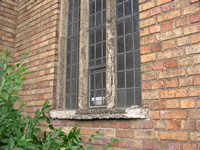
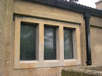
| Figures 6 & 7 Concrete mullions at Scunthorpe Church and (below) a repaired window | ||
 |
Examples of patch repairs on 1930s concrete undertaken for English Heritage are shown in figures 2 and 3. The repair sites were marked out and a 25mm diameter core drill was used to mark the corners. This provided relief at these points and reduced the risk of the arrisses spalling. The depth of the cut-outs was specified as a minimum of 40mm but many areas were taken down to 75mm. This, together with an undercut of 2-4mm on the edges to create a dovetail, helped to lock the repair patches into the existing concrete more securely. Steel reinforcements with previously low cover were either replaced at a greater depth or hammered back into the concrete. The corroded bars were wire brushed to remove the loose corrosion product and not coated. The new high alkalinity concrete will effectively re-passivate the corroded steel. Boards, to match the height of impressions in the original concrete, were fixed across the repair sites and cotton wool was used to seal the interfaces. The repair concrete was sequentially poured in for each board and on the top board a ‘letterbox’ was added to allow it to be filled. The repairs were then externally vibrated to achieve complete filling of the voids.
Repair patches to RC are normally tailored to match the surrounding concrete. To achieve this, the mix of the concrete (cement, sand and coarse aggregate) may be varied, as may its placement, setting and curing time, and its post-cure surface preparation. For instance, the boards may be removed after a few hours and the surface brushed or washed down to remove the cementitious layer. This exposes the aggregate to match the adjacent weathered concrete more closely. Coloured dye may be added to the concrete to improve the match, although this is best achieved by blending different cements and sands in the concrete mix.
One example of this approach is illustrated
by the treatment of concrete decay and
reinforcement corrosion on the external
columns of the chancel at the parish church of
St John and St Mary Magdalene in Goldthorpe
(figure 4). The concrete of this 1914 church
had been badly damaged by a combination of
carbonation and attack from sulphurous fumes
from the nearby Sheffield steelworks in the
early part of the 20th century. This church was extensively repaired in 2001/2 using traditional
concrete repairs and replacement. English
Heritage requested a near perfect colour and
finish match to the original yellowed texture
and ruled out masking the repair with paint,
which is the more usual treatment for concrete
repairs. The match was achieved by varying the
sand and cement content and, in all, involved
30 trial mixes to achieve the best colour and
texture for specific parts of the church. The
final mix was a 1:2:4 ratio of cement, sand and
coarse aggregate with a 0.4 water/cement ratio.
Yellow dye and a water-proofing additive were
also used. A photograph of the completed
chancel is
shown in figure 5. The shutters were
struck after only 12 hours and laitance (the
weakly bound surface residue of cement and
fine particles) was removed by brushing to expose the aggregate. The variable ‘day joints’
which were formed when the concrete was first
cast were faithfully recreated in the repairs to
match the original.
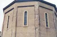
A photograph of corrosion-induced damage to concrete mullions at St Hugh’s, Scunthorpe is shown in figure 6. Again, the RC had been subject to carbonation and chemical attack by sulphurous fumes, in this case from the coking plants that surrounded the town in the middle of the 20th century. Mullions may be either repaired in situ or alternatively, re-cast off site and the sections replaced. An example of repaired mullions is shown in figure 7.
NON-TRADITIONAL REPAIRS
Modern proprietary repair materials normally incorporate polymer-based additives as these tend to have better physical and chemical properties than the conventional cementitious repair materials. For instance, their adhesive and cohesive properties are significantly improved and they may be applied in thin layers to effect patch repairs where spalling has occurred. They can also be more resistant to attack by chloride and other environmental contaminants.
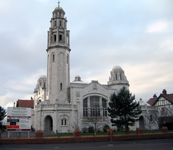
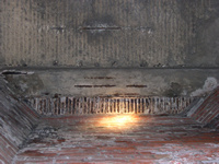
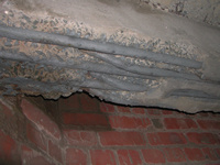
Significant repairs were carried out using polymer-based materials at The White Church, Lytham St Annes in 2004 (see figure 8). The church was constructed in 1903 using mainly stone and brick, but it also contained some of the oldest known RC still in everyday use. The RC comprising the beams and floors within the tower had been subject to corrosion by a combination of carbonation and chloride attack (see figure 9). The church is situated close to the sea and the marine air is used to ventilate the inside of the tower.
Conventional cementitious repairs were considered for this project but these would have involved the complete breakout and loss of the existing (historic) concrete floors. The use of modern concrete repairs, on the other hand, would enable breakout and removal to be limited to the most significantly damaged concrete of the deck soffits and slabs. Pre-bagged, proprietary repair materials were therefore chosen as they were deemed able to provide the strength and corrosion resistant qualities required. A photograph of the RC beams after the loose concrete had been removed and the bars cleaned and primed is shown in figure 10.
 |
 |
|
 |
||
| Figure 8 (above left) The White Church, Lytham St Annes (Photo: Phil Stringer). Figure 9 (top right): Corroding reinforced concrete beams and floor in the tower of The White Church and Figure 10 (lower right): the steel reinforcement after removal of the concrete and the application of a primer | ||
The repair materials were applied to the floors by hand to a thickness of 50-80mm and reinforced with a stainless steel mesh on the underside of the floors. The beams were worked on half a beam at a time. First, formwork was erected around them to form the original profile, then the formwork was filled with water both to wet the original concrete and to wet the boards. After several hours soaking, the polymer-modified repair material was poured in. External vibration was used to remove air voids and the concrete was left to cure for three days. Finally, an anti-carbonation coating was applied over the repaired concrete to slow down future deterioration.
TRADITIONAL VERSUS NON-TRADITIONAL
Reinforced concrete can normally be repaired
using traditional
methods and materials
without resorting to modern proprietary
materials. This normally involves site and
laboratory investigations of the concrete, trial
repairs followed by the major works. Examples
of repairs are given in this article although the
development of repair methods is still ongoing.
Modern proprietary materials often have improved physical and chemical properties to traditional cementitious materials and the same physical benefits. In particular, chloride and carbonation ingress resistance can often be achieved with significantly less thickness and hence weight. Unfortunately, modern materials weather differently to the original concrete and do not support the algal and lichen growth. The result of this when used on external surfaces is a patchwork finish, which may then require painting to ‘mask’ the repairs. This is sometimes unacceptable to the conservation industry. However, modern proprietary repair materials do have a place in repairing RC internally or in areas hidden from view in historic concrete churches.