


Stiffness in Timber Floors and Ceilings
Jeff Stott
 |
|
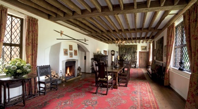
| Primary and secondary floor structure exposed in the ceiling of the Long Room at Chenies Manor, Buckinghamshire (Photo: Peter Mukherjee, iStock.com) |
The reduction in the performance of suspended timber floors in historic buildings, whether perceived or real, continues to absorb many hours of structural analysis. Sometimes the drivers are the obvious ones, like failed principal beams that disturb plaster finishes, sometimes they are less obvious, like the tinkling of a chandelier; either way, the problem exists.
The safe approach is to follow the repair principles of the Society for the Protection of Ancient Buildings, especially in terms of minimum intervention. However, for this to be successful, it is first necessary to understand all the relevant facts and influences, including human perception.
Problems with suspended timber floors usually relate to one of two structural design considerations – strength and stiffness (serviceability). The solutions for reduction in strength due to various external influences are normally clear but can be difficult to execute (see Robin Russell’s ‘Structural Timber Repairs’ in The Building Conservation Directory 2013). On the other hand, the solutions for correcting ‘lively’ floors, which are the focus of this article, are generally more complex and client expectations are often difficult to satisfy.
CAUSES AND EFFECTS
All suspended timber floors deflect to some degree with changes in dead load and the more complicated live loading. In modern designs, the movement is barely noticeable to a person walking across the floor. However, in some cases, especially older floors, there may be a discernible bounce. In the worst cases the vibration can cause cracks in fine historic plasterwork on the ceiling below, threatening its survival. Inadequate stiffness can also make a timber structure susceptible to vibration from less direct sources such as traffic, live music performances and machinery, so plaster ceilings with no floor above may also be liable to similar issues.
Before any intervention can be contemplated, it is essential to fully understand the nature of the structure, its condition and the cause of the problem. Defects may be inherent – undersized primary beams or joists for example – or the result of changes which have occurred over time, such as holes and notches cut for services, or due to the effects of decay. Changes in loading may also have occurred, caused for example by a change in the use of the floor above that may in turn require the addition of new equipment. Partitions added on to a floor could alter load paths, transferring new loads onto the structure, while the removal of partitions below may have increased the spans.
It is also important to understand the likely consequences of the condition, including not only the physical effects on historic fabric such as plasterwork, but also the perceived effects and expectations of the client. According to Annex B of ISO 2631-pt2 2003, which gives guidance on human response to building vibrations:
Human response to vibration in buildings is very complex. In many circumstances the degree of annoyance and complaints cannot be explained directly by the magnitude of monitored vibration alone. ...The basic human response to vibrations in buildings is adverse comment.
This suggests that human sensitivity to vibrations in structures is subjective and therefore difficult to satisfy. It appears that, apart from the physical construction survey, vibrations in the suspended floor need to be measured to enable a focussed report to be communicated to the client. Otherwise it is possible to spend a lot of money trying to fix a lively floor with little perception of improvement.
 |
 |
|
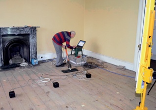
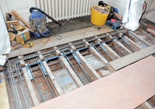
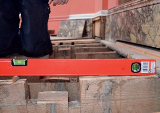
| Recording vibrations from a dynamic excitation device (in this case a drophammer) to analyse the performance of a timber floor: the data can help assess deflections, stiffness and dynamic responses | Steel tensioning to improve the structural performance of over-spanned joists |
ASSESSMENT
Every historic timber structure is unique. Although it should be possible to predict a beam’s deflection from its dimensions based on an assumed modulus of elasticity, in practice such calculations are unreliable. The size and location of knots, the quality and strength of the timber, and the presence of decay, all impact on its performance. The strength and performance of the structure as a whole is also affected by the integrity of connections, whether primary or secondary (from beam to wall, and from joist to beam, for example). A repair previously carried out on one project rarely suits another. Although the structure may appear to be similar, the variables are so great that the probability of an exact fit is low.
Although obvious, it is worth stressing that surveying the situation is essential. The uniqueness of the construction needs to be understood for the repair to be a complete design that takes account of the performance required from the structure, the longevity required, and the ease of maintenance and accessibility, as the repair might require future modification or, indeed, reversal. The design must also be based on an accurate assessment of how much fabric needs to be disturbed.
 |
|
| Dynamic analysis of the Octagonal Gallery at Mount Stewart House: the top three diagrams illustrate the mode shapes associated with the first three natural frequencies of the structure, the bottom image is a finite element model which represents the predicted deflection of the structure with a uniformly distributed loading applied to one half of the gallery. |
A survey starts with the preparation of accurate drawings, recording the current structure, noting any obvious defects. An assessment of existing records can often shed further light on past alterations. Some evaluation of the actual deflection is also required to give a fuller picture of how the structure is performing.
The standard method of measuring deflection involves constructing a stable scaffold to within 50mm of the underside of the ceiling and then measuring the deflection under live loads using a dial gauge fixed between the top of the scaffold and the underside of the ceiling. If the scaffold is rigid, the dial gauge is sufficiently accurate to record deflections of less than 0.01mm. However, to achieve the stability required it is best if the scaffold is built off solid ground, which is not always possible.
Investigation and analysis techniques are being developed that can model the dynamic performance of suspended timber floors in three dimensions. A dynamic floor appraisal that records accelerations of a structure against known excitation forces provides more information than simple static tests.
To explain the difference between static stiffness (EI) and dynamic response – accelerations of the structure – imagine standing still in the middle of a floor while loads are applied; you experience static stiffness when the floor deflects but not necessarily the bounce or response. It is the combination of EI, mass, boundary conditions and damping which creates the dynamic response and thus human perception of it. Therefore the dynamic analysis is a more accurate method. Using this approach data can be collected that can identify the natural frequencies of the floor as a whole that account for the uniqueness of its construction.
Mann Williams Consulting Engineers have carried out a number of tests on historic floors to develop the technology. Data is provided using an appropriate dynamic excitation device at intervals across the floor surface while the vibrations are recorded from around the room. Deflections, stiffness and the dynamic responses of the structure can be modelled from the data gathered, allowing the true characteristics of the whole floor assembly to be analysed.
Not only can this provide a clear picture of the existing structure and its anomalies, but it can also be used to explore various ‘what ifs’, such as the effect of better load management or the introduction of reinforcement, to give a better understanding of the potential of the existing structure. Dynamic testing and modelling recognises and quantifies the uniqueness of timber structures and highlights the failures of simple analyses based on theoretical magnitudes of deflection. It can see the structure as a whole, identifying various areas of damping and areas that can be exploited to reduce vibration. Essentially it can give a better idea of whether or not the vibration of the floor can be improved within a given budget.
INTERVENTION AND MITIGATION
Solutions to excessive deflection under dynamic load fall under two categories: load management and structural improvements. The former includes measures to reduce the loading or better distribute it across a wider area, or to bypass defective elements altogether. The latter includes repairs and, if necessary, alterations to improve the performance of the structure. However, the ability to carry out repairs to principal beams and floor or ceiling joists is almost invariably confined by the historic fabric that surrounds them.
Repairs should be honest and disturb the surrounding fabric as little as possible. Ideally they should be limited to within the depth of the floor zones. It is sometimes possible to supplement the timber with steel splints fixed to the sides of the joists to improve shear and bending strength and stiffness. On a beam supporting secondary joists, however, this may be impossible without removing all of the original tenons from the floor joists, causing substantial damage to its historic significance. Repairs may be needed that improve the bearing while maintaining honesty, protecting the original fabric as much as possible and allowing for a degree of reversibility (a complex subject in its own right).
The following cases further illustrate some of these options.
MOUNT STEWART, NORTHERN IRELAND
Service notches can severely disturb the performance of suspended timber floors both in terms of strength and serviceability. While most plumbers and electricians are aware of this now, in the past there was an arrogant disregard for structure when new services were installed within floors. An example of the problems caused by notching is the drop in the floor of the Octagonal Gallery above the central hall at Mount Stewart, an 18th-century mansion house owned by the National Trust. This drop was severe enough to bring the floor’s safety into question, not just because of the dramatic distortion but because of the structure’s response to footfall.
 |
 |
|
| The Octagonal Gallery at Mount Stewart, Northern Ireland after partial opening up revealed the extent of service notching (Photo: David McClimond/National Trust) | The original structural design of the gallery was perfectly sound but the service notches had caused the marked drop in the gallery floor shown here. |
For the gallery to work unsupported on the balustrade side, there had to be load-sharing between the joists, fanning out from the wall, and a central ring beam acting in a complicated display of compression and tension. The central ring beam is not a perfect circle but is elliptical or a stretched octagon and would naturally have difficulty maintaining the structure in place along the near straight sections that relate to the major axis. The joists need to function as cantilevers with a particular stiffness to ensure these long straight sections are not overloaded and the connections between joist and ring beam need to have a high degree of fixity. If the joists deflect too far, the stresses in the inner beam can change to the point of inversion; this in turn brings the effect of the balustrade into question. Notches in the joists could be catastrophic but notches there are – or were – causing increased deflections and locally high stresses in the joists.
The structural concept of the original design was correct: it was the interference that was damaging and this has now been corrected by filling the notches and installing straps across them to ensure the tension is catered for and by improving the fixity between joists and ring beam. In addition, the gallery has been jacked into position, connections improved and timber repairs completed, leaving the gallery structure nearer to horizontal with an 80 per cent improvement.
Simply by reinstating the loss, the repair successfully addressed the two structural concerns particular to the structure: degradation and serviceability/vibration.
CHATSWORTH HOUSE, DERBYSHIRE
An early solution to the problem of vibration in suspended timber floors was the use of cast iron flitches in the staterooms at Chatsworth. A flitch had been inserted between split timber beams (the beams appear to have been cleaved rather than sawn, possibly indicating the work was carried out in-situ). The flitch is a cast inverted ‘T’ with a slot formed in its base. This slot ends with an anchor block at each bearing against which a rod is tensioned. The use of cast iron probably dates the repair to around the mid-19th century. There is no evidence so far that would link the repair to Joseph Paxton, designer of the 1851 Crystal Palace, but as he was head gardener at Chatsworth from the 1820s and was designing the Chatsworth greenhouses in 1832, it is hard not to make the link.
The evidence that this early flitch design was used as an attempt to mitigate the liveliness of the floor is clear. It was not installed because of decayed bearings or because the beams were overstressed; even now the timber is in good condition throughout its length. The timber is oak, spanning 9m at a depth of 400mm. The phrase ‘dozy beam’ has been used at Chatsworth to describe some principal beams’ soporific attempts to do a mighty job. However, these beams would have had difficulty coping with dynamic loads from the start, becoming exhausted over time.
Unfortunately, the cast flitch would probably have done little to improve users’ perception of floor vibration. There are so few bolts used to connect the timber to the cast flitch that load transfer between the materials would have been negligible, preventing them from working as a composite whole.
The two examples above show that liveliness in a historic, suspended timber floor can be the product of an inherent defect and may be worsened by interference with the structure. If a problem can be exacerbated by interference, this raises the question: can it be improved by interference? Can we mitigate vibrations in historic floors that have their own unique natural frequencies, depending on their depth, span, and connections? And can we do enough to satisfy those sensitive human perceptions of vibration noted above?
THE VYNE, HAMPSHIRE
 |
|
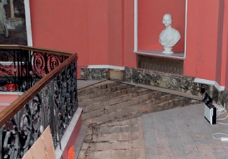
| The Oak Gallery at The Vyne, Basingstoke: the heavy busts which line the gallery oscillated when members of the public walked through it. (Photo: Nadia Mackenzie/ National Trust) |
In the oak gallery at The Vyne in Basingstoke, floor vibration disturbed timber columns that supported heavy stone busts. When the public walked through the gallery the busts oscillated back and forth into the room as though nodding. The floor is based on a series of principal beams carrying secondary floor joists which in turn support tertiary joists above, like counter-battens, to which the floorboards are fixed.
A simple calculation showed that the principal beams were slightly undersized for the span, resulting in a live-load deflection that promoted a low frequency in the floor vibration. A failure to think laterally would have resulted in the complete lifting of the floor finish in an attempt to stiffen the principals. This would have been difficult in view of the ornate plaster ceiling below and the tennoned joints of the floor. However, because the bust supports sat near the walls it was apparent that the tertiary joists could be cut within about 500mm of the walls thus preventing the maximum oscillation within the principal beam transferring to the supporting tertiary joists below the busts.
HOLISTIC SOLUTIONS
The simple solution identified at The Vyne would have been apparent immediately using the dynamic testing approach currently being developed, and it is clear that this technology will be invaluable for more complex floor structures.
Building structures need to be considered holistically, not only in terms of the interaction between structural components, but also in terms of their use and the client’s requirements. Practicalities of construction need to be taken into account, and the likely benefits of each solution need to be weighed against their cost, both financially and in terms of their impact on the significance of the structure.
Ultimately, the most appropriate solution can only be identified through close liaison between the whole conservation team – client, builder, quantity surveyor, architect and engineer.