Basic HTML Version


t h e b u i l d i n g c o n s e r v a t i o n d i r e c t o r y 2 0 1 2
4 3
1
Professional services
Choice of surveyor
Different surveyors specialise in different
scales and types of work, so knowledge of the
required outputs and attention to historic
detail is essential. A mixed portfolio that
includes small and medium sized projects and
strong experience of historic fabric is usually a
good clue to a surveyor’s suitability.
Specification of output
Some time-consuming processing occurs
after a laser survey is undertaken. It is
therefore more important than with
older survey methods for the professional
to specify exactly what is required.
A specification for conventional output
of 2D drawings should include:
• a description of the purpose of the survey
• the physical extent of the work,
including roofs and voids
• the point density and point tolerance
• the 2D drawing series of plans,
elevations and details, if necessary using
photographs or pre-existing survey
records to help clarify the work
• parameters that describe the tolerance
of detail on the drawings.
The tolerance of the detail can be described,
for example, by the required scale of drawing
(1:100 up to perhaps 1:5). Quoting this will help
the surveyor to decide how much detail to
include. Further guidance is given in sections
5 and 7 of English Heritage’s Metric Survey
Specifications for Cultural Heritage (see
Recommended Reading).
It is important to define what
project-specific detailed drawings may
be required at the beginning of the
survey, so that the surveyor can adjust
the density of data collected and set-up
points to focus on specific needs.
From laser scan to drawings
The scan collects large volumes of data
which are stored in compressed format on
the device’s hard drive. The data is then
downloaded and processed to become the
point cloud in a process known as registration,
undertaken using software such as Cyclone™.
During this process, spurious points are
removed and the point data is converted to
a standard transfer format. The point cloud
might typically contain between one and
ten billion points that describe the building
surfaces inside and out.
The process of reducing this to 2D
drawings or 3D models usually involves
thinning this to a lower density. In the case
of 2D drafting, a cutting plane is defined and
the data exported to form the drawing using
proprietary software such as CloudWorx™. The
process of creating the 2D image, known as
vectorisation, is a simple but rather laborious
process of join-the-dots. An enlarged detail is
shown in Figure 3.
Clearly, the greater the accuracy required,
the less thinning-out is undertaken and the
more dots there are to join. So it is essential
that the surveyor knows what resolution is
required from the start. Quoting a drawing
scale is still a good way of expressing this, even
though CAD effectively functions at 1:1.
Scanning is particularly suited to
recording highly irregular surfaces such
as timber frames and medieval stonework,
and their individual components can be
clearly identified from the scan. However, it
is often necessary to use photogrammetry
in conjunction with laser scanning to trace
more uniform areas of brick, terracotta or
stonework. If this level of detail is required,
for specifying repairs to individual stones for
example, then this requirement should be
stated at the outset for including in the pricing.
The use should also be discussed in detail with
the surveyor prior to site work.
Ownership and transfer of data
Normal principles of ownership and
intellectual property usually apply to the
output. The survey company retains this and
the purchaser is typically given a royalty-free
licence to use it for the purposes defined.
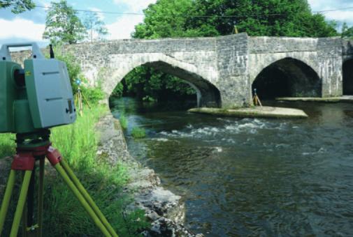
Figure 2 Typical survey equipment showing common objects mounted on tripods to correlated datasets taken from different locations – from either side of the river for example
Figure 3 Detail of stonework drawn at 1:50 and enlarged to
show discrete linework (Image: Greenhatch Group)