


 58 / 208

5 6
T H E B U I L D I N G C O N S E R VAT I O N D I R E C T O R Y 2 0 1 5
T W E N T Y S E C O N D E D I T I O N
2
BUI LDING CONTRACTORS
and ties can be inserted for this purpose.
Drilling into the back and/or sides of the
breakout and fixing cramps or ties using
an epoxy resin adhesive is usually effective
(Figure 4). For marine environments, the
additional reinforcements should be in
stainless steel, otherwise mild steel should
suffice. Increasing the depth of the repair
patch, dovetailing the sides and roughening
the base of the breakout should all provide
additional mechanical bonding.
Breaking out the concrete
Once an area of damaged concrete has been
identified it should be marked out using
straight lines. For board-marked concrete,
horizontal lines should run along the edges
of the board marks. A 10–20mm diameter
diamond core drill (depending upon the size
of the repair) should be used to mark the
corners of the breakout. The holes provide
relief at these points and reduce the risk
of spalling to the arrisses. Where severe
delamination and corrosion has occurred, the
depth of the repair areas should be specified
as a minimum of 40mm and the base left
rough. The edges of the breakouts should be
cut using a diamond blade with an undercut
of 2–4mm and to a depth of 25mm to create
a dovetail to improve the mechanical bond
of the repair to the parent concrete. Each
cut should run up to the drilled holes at
the internal angles. On no account should
any cut pass the edges of the holes. The
remaining concrete can then be extracted
using a mechanical breaker, typically 10–25kg,
depending upon the area to be removed.
Larger areas may require more severe
measures to remove the damaged concrete.
Steel reinforcements with insufficient
cover (typically less than 15mm), or which
have suffered significant loss-in-section,
may be cut out and replaced with new steel
at greater depth (Figure 5). An alternative, if
the thickness of the steel is sufficient, is to
hammer any low-lying reinforcement back
deeper into the concrete body to provide
increased cover. However, a structural
engineer should be consulted before starting
any works that might affect the structural
performance of the reinforcement.
Any corroded bars should be
mechanically cleaned to remove the loose
corrosion product but not coated as the high
alkalinity of the new concrete repair will
effectively re-passivate the corroded steel. By
contrast, modern repair mortars do not have
the high alkalinity required so where these are
used all reinforcements must be grit blasted
before applying protective coatings to the
cleaned steel.
Preparing the shutters
Concrete repairs should be placed using
shutters (wood grained boards, plywood or
metal shutters) similar to that used for the
original concrete so that the new surface
matches the original. This also enables air
pockets and voids to be removed and helps
to ensure that the repair completely fills the
space. However, in some circumstances, such
as small patch areas or areas with uneven
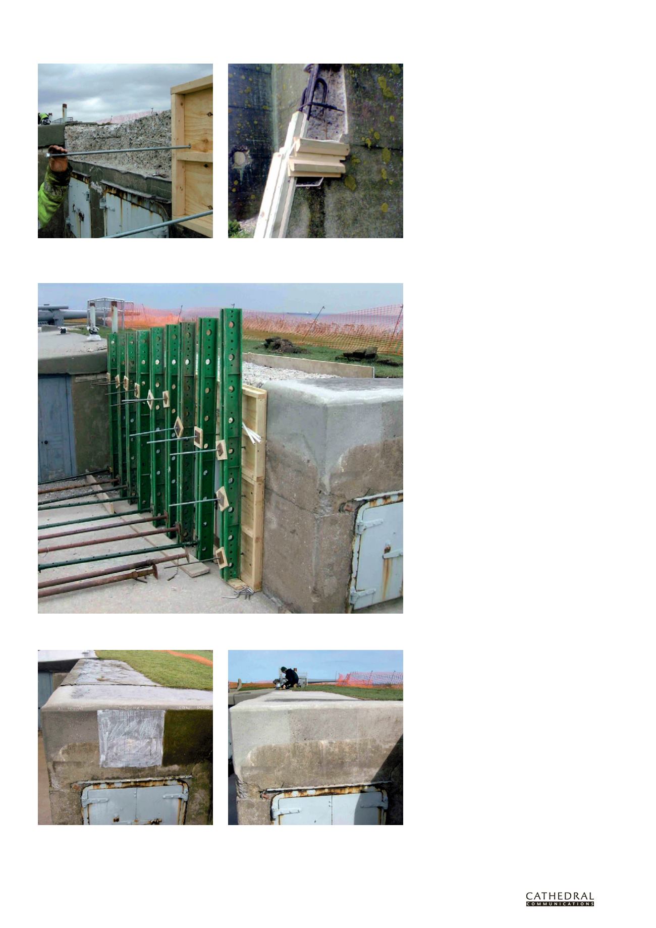
Figure 9 For large repairs, additional steel support will be needed to withstand the weight of the concrete repair
materials.
Figure 10 Trial showing the application of surface treatments to new repair concrete and, right, slight
darkening of the treated concrete repairs after three months’ exposure. Left to right: as found, live yoghurt and
cow dung.
Figure 7 The next best method is to use plugs or rock
anchors to fix the shutters internally within the breakout.
It is particularly useful for larger scale repairs.
Figure 8 Additional wooden formwork was needed to
support the shuttering for this concrete buttress.