


Concrete Repairs
Traditional Methods and Like-for-like Materials
David Farrell and Chris Wood
 |
|
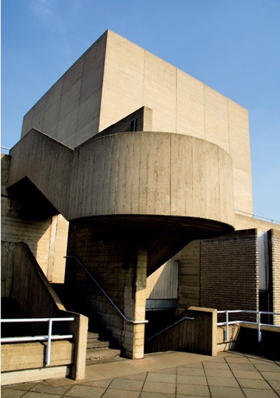
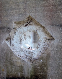
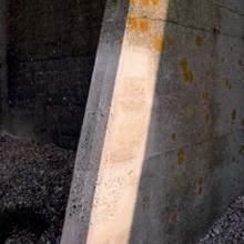
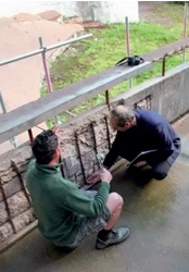
| Figure 1 A staircase at the National Theatre, London (Photo: NAES, iStock.com) |
Where historic fabric requires conservation, damaged material is usually repaired in situ, and any new material and details required are expected to match the existing on a like-for like basis wherever possible. However, where concrete is concerned the European standard Products and Systems for the Protection and Repair of Concrete Structures (EN1504-5:2013) recommends that all repair mixes should come ready-bagged from certified factories.
Almost all materials certified under this standard are modern ‘concrete repair mortars’ not concrete. While their use on historic buildings and structures may be justified in some instances, like-for-like repairs will often perform at least as well and any decision to vary the materials must be based on a sound understanding of the options.
BACKGROUND
Historic concrete includes reinforced concrete (RC) and bulk (non-reinforced) concrete (BC); a material which has been widely used for military facilities in the past. RC generally suffers from deterioration (mainly carbonation and chloride attack) of the concrete which subsequently allows the steel reinforcements to corrode; this results in cracking and delamination of the concrete ‘cover’. BC tends to suffer more from ground movement and differential expansion and contraction which causes cracking and slippage of larger sections of concrete. Different pours of BC (laid down at different times) sometimes become detached from each other resulting in movement. Both types of concrete suffer from weathering by pollutants in combination with rain and mould/algal growth which mar their appearance.
Like-for-like patch repairs to concrete have been carried out in the past but many of these are now failing for a variety of reasons. Some repairs were too shallow and did not adequately address the underlying corrosion of the reinforcements, or they were not ‘mechanically bonded’ to the host concrete (feather edging, for example, may result in cracking and shrinkage). There have also been difficulties matching the colour and texture of the original material. These problems, along with the desire for easy and quick repair methods suitable for unskilled labour, led to the development of modern repair mortars which are now widely used for repairing concrete. Many of these contain polymer modified components which can be applied as thin layers to delaminated surfaces and adhere strongly to the host material. These repair mortars are not popular with the conservation industry as they introduce different materials and do not weather-in to match. Their longevity is also uncertain when used in combination with the parent concrete.
The adaptation of traditional types of repair in England has been growing since 2001 when the church of St John and St Mary Magdalene, Goldthorpe, South Yorkshire was successfully repaired and conserved. Additional trials and testing were carried out at Tynemouth Priory Coastal Battery (bulk concrete structures dating back to the 1880s) and the Listening Mirrors, Dungeness (reinforced concrete dating from the 1930s). Other developments and testing carried out in this period are discussed in English Heritage’s Practical Building Conservation: Concrete (see Recommended Reading). Several ongoing repair projects where like-for-like repairs are being implemented are referred to below. However, the main focus of this article is the National Theatre, London where an initial investigation of the concrete was carried out and methods and materials were specified for traditional repairs. These were further improved by the contractor and many smaller scale repairs are currently being carried out.
THE NATIONAL THEATRE
Built in 1976, mainly of steel reinforced concrete, the National Theatre (listed Grade II*) is an iconic building on London’s south bank. Its concrete is generally in good condition but over the years it has suffered some deterioration. In places the steel reinforcements had insufficient cover causing the concrete to crack or spall, while in others cracks were caused by thermal movement and subsidence. Mechanical damage had also occurred where fixtures have been added and removed.
 |
 |
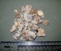
| Figure 2 Sample of concrete from the National
Theatre exhibiting naturally round and broken
aggregate, with centimetre measure
|
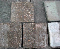
Figure 3 Concrete test flags using different mixes
and with retardants applied to one side only. Half
the surfaces were wire brushed after early breakout
(12 hours). |
The theatre is currently undergoing alteration and its concrete is being repaired. Because of its historic status the repairs are being carried out on a like-for-like basis as far as possible. More modern methods and materials are only being employed where this is not possible, or where a different approach is sure to result in a better repair.
To replicate the original mix accurately, documentary sources were checked first, then samples were taken for analysis.
Documentary assessment The only documented evidence of the original constituents of the concrete used was the ‘Bill of Quantities for Superstructure to National Theatre (Phase 2)’ which was dated 1970, six years before it was built. From this it was concluded that the ‘white’ concrete forming the external board-marked (wood grain), bush hammered and fair-faced concrete was originally intended to comprise the following:
- 80% Snowcrete (WPC) and 20% ordinary Portland cement (OPC)
- Leighton Buzzard sand as fine aggregate
- Newmarket flint (¾” to ⅜”) as large aggregate (angular or rounded crushed rock) – specified at the time to be obtained from Allen Newport in Fordham, Cambridgeshire.
- The mix was generally described as between 1:8 and 1:3.3 (by dry weight) cement to total aggregate. However, other sections in the book describe their ratio as being between 1:7 and 1:4.
Visual assessment A view of the aggregate from a fair-faced core sample is shown in Figure 2. This shows the large aggregate to be mainly rounded stones, much of it broken. The size distribution of the large aggregate was 11-22mm, corresponding with the ⅜” to ¾” specified. Particles of the sand were separated out from the concrete and measured. Typical fine aggregate diameters of 0.3-0.8mm were found.
Geological assessment Further analysis of aggregate from the broken sample was carried out at Aberdeen University by Natalie Healy, a postgraduate researcher whose report is summarised below:
The samples of Newmarket Flint aggregate consist of concrete and poorly sorted quartz and feldspathic grain (sandy) matrix derived from an Arkosic sandstone. The sample contains rounded clasts of various sizes and lithologies including flint, shelly debris and chalk and few clasts of crystalline quartz. Clast lithology has been identified using standard mineral identification techniques including Moh’s scale of hardness.
Clast types identified include:
- Predominantly orange and brown and few grey clasts of silica rich, cryptocrytalline flint identified by a hardness of 7 and characteristic conchoidal fracturing. Clast size ranges from 3mm-20mm.
- Clasts of silicified indeterminate Pectin shells (scallops) ranging in size from 5mm-<10mm.
- Few clasts of iron stained translucent crystalline quartz.
- Few clasts of fine grained, well cemented chalk identified by a hardness of 3.
- Rare clasts of black, lustrous, soft organic material possibly produced from fossilised wood.
Sandy matrix
The concrete matrix comprises poorly sorted rounded grains of quartz, feldspar, lithics and few green coloured grains of the mineral glauconite. Matrix sandstones may be sourced from the overlying Upper Greensand Formation which outcrops nearby Fordham.
MATCHING THE ORIGINAL CONCRETE
The lack of availability of the original constituents can often present problems for the conservation of historic concrete. Early concrete aggregates (pre-1960s) were normally sourced from local suppliers which were themselves supplied by local quarries, but many have since been ‘worked out’ or closed. So the first task was to see if these constituents were still available:
 |
 |
|
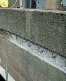
| Figure 4 For bulk concrete or where different pours of concrete have been applied, stainless steel cramps may be inserted to bind the layers together. | Figure 5 The back of the breakout should be left rough to improve the bond of the new repairs. Additional steel reinforcement might be needed in some patches. |
Cements – White Portland Cement (WPC) is ubiquitous, although it is likely to be much finer than that used in 1976 and will therefore have different setting properties. Ordinary Portland cement (OPC) will also be finer and will have different properties.
Sand – Leighton Buzzard sand is still available from the Leighton Buzzard Silica Sand Company. It comes in 25kg bags in different colours. The colours most likely to match the original for the NT are the white or yellow. The sand comes in various grades, but the specification (0.25-0.71mm) seems the closest match.
Large aggregate – Fortunately, Allen Newport Ltd is still operating in Cambridgeshire; they do not now supply ready mixed concrete but they still operate the same quarry that supplied the aggregate in 1976. This is now supplied as 10mm or 20mm – the latter corresponding to what was probably used for the NT in 1976.
The next stage was to prepare samples of concrete (the ‘slab library’, see Figure 3) using the previously identified constituents in varying combinations and quantities. Wooden mould boxes (approximately 300 x 300 x 50mm deep) were constructed to cast them in. For fair-faced concrete, plywood is normally suitable, but for replicating board-marked concrete, rough sawn boards of Douglas fir were used as specified in the bill of quantities. This work is best carried out in the workshop and the samples subsequently left outside to cure.
Typically, 10-15 test flags should be cast for a single type of concrete using different combinations of cement (WPC and OPC), different sands and different types and sizes of aggregates to match those of the original concrete, bearing in mind that for thinner repairs, the size of the aggregates may need to be reduced. Concrete analysis from the NT showed that the aggregate size was up to 20mm but it was considered prudent to reduce this to 10mm for thinner repairs (35-40mm deep).
Colour match is best achieved using different combinations of sands, and sometimes even cements. The original bill of quantities stated 80 per cent WPC and 20 per cent OPC. However, as even a small amount of OPC combined with WPC can turn the repair concrete grey, samples included some without OPC. The slabs were left outside for a period of weeks to determine their final colour. In some circumstances colouring agents may be used to help match the original ‘aged’ concrete, and it is often worth evaluating these in some of the samples.
Where a weathered surface is to be matched, the surface of the concrete may also be wire-brushed or abraded after it has been struck from the boards, as this removes cementitious material and exposes the aggregate. Other finishes may also be applied at this stage, for example where a bush-hammered surface is to be replicated (a textured finish made by blows from a studded metal hammer). However, manipulating the surface can be almost impossible if it has set too hard, so it may be necessary to apply a retarder to the surface of the boards when casting the concrete. To assess whether retarders are necessary, the bottom (boardmarked) shutter of each slab should be coated and the top shutter left alone (with just a release agent). The moulds should be broken out early (typically 12 hours) and half of each side (top and bottom) of the slab (retarded and free) should be wire brushed (or mechanically abraded) to assess the set. Setting is slower in the colder months so retardants may not be needed whereas in the summer months they may be essential. Damp covers should be left over the slabs after this work so that the slabs can fully cure.
Trial mixes for the test slabs for the NT are given in the table below.
The cured test slabs can be used as a visual reference library so that different types, textures, colours and degrees of weathering around the building can be suitably matched as the work progresses. This is particularly important where the concrete has variable texture and colour or where it has been subject to varying degrees of weathering. This preliminary work will help the contractor to establish optimum repair methods prior to initiating the conservation work.
TRIAL MIXES FOR THE NT TEST SLABS |
|||
Mix No. and Ratio |
Cement |
Sand |
Aggregate |
1 (1:2:3) |
80:20 WPC:OPC |
Leighton Buzzard white |
10mm Newmarket flint |
2 (1:2:3) |
80:20 WPC:OPC |
Leighton Buzzard white |
20mm Newmarket flint |
3 (1:2:3) |
80:20 WPC:OPC |
Leighton Buzzard yellow |
10mm Newmarket flint |
4 (1:2:3) |
80:20 WPC:OPC |
Leighton Buzzard yellow |
20mm Newmarket flint |
5 (1:2:3) |
100% WPC |
Leighton Buzzard white |
10mm Newmarket flint |
6 (1:2:3) |
100% WPC |
Leighton Buzzard yellow |
10mm Newmarket flint |
7 (1:2:4) |
80:20 WPC:OPC |
Leighton Buzzard white |
10mm Newmarket flint |
8 (1:2:4) |
80:20 WPC:OPC |
Leighton Buzzard yellow |
10mm Newmarket flint |
9 (1:2:4) |
100% WPC |
Leighton Buzzard white |
10mm Newmarket flint |
10 (1:2:4) |
100% WPC |
Leighton Buzzard yellow |
10mm Newmarket flint |
REPAIRING DAMAGED AREAS
Before any repairs are initiated, it is important to determine whether the original structure contains design faults that have resulted in premature deterioration of the structure. Faults might include concrete roofs with inadequate waterproofing or rain run-off features without a suitable drip. Alterations to listed structures are usually permitted under such circumstances.
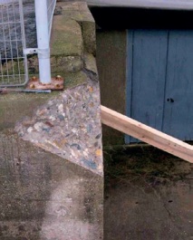
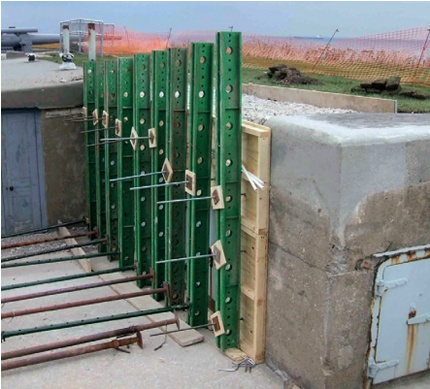
Traditional concrete repair materials, using similar constituents to the original, should have a lifetime similar to that of the structure to be repaired (many decades for high quality concrete). However, traditional concrete repair materials do not have the enhanced adhesive and cohesive properties provided by modern repair mortars with polymer additives, so additional mechanical means are required to improve the bond. For repairs to reinforced concrete (RC), the presence of steelwork within the concrete breakout assists in the mechanical bonding. For bulk concrete (BC), particularly where different pours have not bonded, cramps and ties can be inserted for this purpose. Drilling into the back and/or sides of the breakout and fixing cramps or ties using an epoxy resin adhesive is usually effective (Figure 4). For marine environments, the additional reinforcements should be in stainless steel, otherwise mild steel should suffice. Increasing the depth of the repair patch, dovetailing the sides and roughening the base of the breakout should all provide additional mechanical bonding.
Breaking out the concrete
 |
 |
|
| Figure 6 The best method of fixing the shutters is using external supports, although this is often impractical. | ||
Once an area of damaged concrete has been identified it should be marked out using straight lines. For board-marked concrete, horizontal lines should run along the edges of the board marks.
A 10-20mm diameter diamond core drill (depending upon the size of the repair) should be used to mark the corners of the breakout. The holes provide relief at these points and reduce the risk of spalling to the arrisses.
Where severe delamination and corrosion has occurred, the depth of the repair areas should be specified as a minimum of 40mm and the base left rough. The edges of the breakouts should be cut using a diamond blade with an undercut of 2-4mm and to a depth of 25mm to create a dovetail to improve the mechanical bond of the repair to the parent concrete. Each cut should run up to the drilled holes at the internal angles. On no account should any cut pass the edges of the holes.
The remaining concrete can then be extracted using a mechanical breaker, typically 10-25kg, depending upon the area to be removed. Larger areas may require more severe measures to remove the damaged concrete.
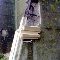
Steel reinforcements with insufficient cover (typically less than 15mm), or which have suffered significant loss-in-section, may be cut out and replaced with new steel at greater depth (Figure 5).
An alternative, if the thickness of the steel is sufficient, is to hammer any low-lying reinforcement back deeper into the concrete body to provide increased cover. However, a structural engineer should be consulted before starting any works that might affect the structural performance of the reinforcement.
Any corroded bars should be mechanically cleaned to remove the loose corrosion product but not coated as the high alkalinity of the new concrete repair will effectively re-passivate the corroded steel. By contrast, modern repair mortars do not have the high alkalinity required so where these are used all reinforcements must be grit blasted before applying protective coatings to the cleaned steel.
Preparing the shutters
Concrete repairs should be placed using shutters (wood grained boards, plywood or metal shutters) similar to that used for the original concrete so that the new surface matches the original. This also enables air pockets and voids to be removed and helps to ensure that the repair completely fills the space. However, in some circumstances, such as small patch areas or areas with uneven surfaces, hand-placing the concrete may be adequate (Figure 4).
 |
 |
| Figure 7 The next best method is to use plugs or rock anchors to fix the shutters internally within the breakout. It is particularly useful for larger scale repairs. | Figure 8 Additional wooden formwork was needed to support the shuttering for this concrete buttress. |
 |
|
| Figure 9 For large repairs, additional steel support will be needed to withstand the weight of the concrete repair materials. | |
 |
 |
| Figure 10 Trial showing the application of surface treatments to new repair concrete and, right, slight darkening of the treated concrete repairs after three months’ exposure. Left to right: as found, live yoghurt and cow dung. | |
The shutters should be cut to size to cover the repair area. For board-marked concrete, rough-sawn wood (such as Douglas fir) should be cut to match the height of the original board marks. The boards should be butt-jointed together and a foam strip (gasket) applied around the circumference of the repair patch (between the shutters and the parent concrete) to prevent laitance seeping out.
By fixing hinges to the lower edge of the top-most board, a letterbox arrangement can be created at the top of the repair patch to allow the repair to be filled.
The shutters should be coated with either a release agent or retarders prior to use.
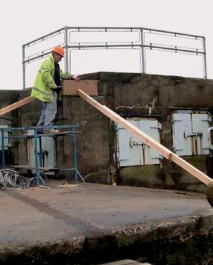
The best method of holding shutters in place for smaller repairs is to use external supports (Figure 6) although this is frequently impractical. For larger repairs the shutters need more substantial fixings to support the weight of the repair concrete.
The next best method of supporting the shutters is to use rock anchors that are ‘hammer fixed’ into the back face of the repair areas with threaded bars to secure the shutters (Figure 7). The threaded bars are removed after the repair has set and the fixing holes (which are now in the new repair patch) filled in. Other types of fixings may be plugged into the repair areas for smaller repairs.
Alternatively, shutters can be supported outside the repair patch using fixings to the parent concrete; however, this results in additional holes in the parent concrete that require filling afterwards.
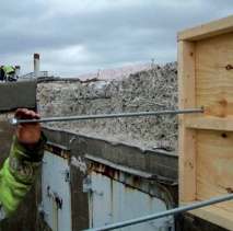
Additional formwork may be required for complex repairs (Figure 8), and for larger areas of repair steel beams may also be required to support the weight of the repair concrete, (Figure 9).
Placing the concrete
The specified mix of the concrete should be selected from the slab library to match the colour and texture of the particular area to be repaired. A typical composition may be 1:2:3 (cement:sand:aggregate), mixed with a water:cement ratio of around 0:4. Additives, such as styrene butadiene rubber (SBR) may be beneficial in minimising the water:cement ratio while maintaining the workability of the concrete repair, unless it is likely to discolour the concrete. SBR also increases the bond strength and provides water resistance to the concrete repair.
The repair area should be suitably wetted before the repair is made. The concrete should be placed through the letterbox at the top of the shutters (in batches) and a poker used to vibrate the mix to remove air pockets. This should continue until the mould is completely filled. The repair should then be left to set, typically for 12-24 hours, before removing the shutters. The exact time depends upon the environmental conditions (mainly temperature), together with the thickness and bulk of the repair. The time may be shortened (early breakout) if the concrete surfaces require finishing treatment.
If the repair is to be hand-placed, a cement slurry primer should first be used on the back of the breakout and the repair gradually built up using a number of layers. Damp covers should be placed over the repairs to complete the hydration reaction.
Surface finish
Concrete repairs frequently produce a lighter colour than the parent concrete as, until their surfaces have weathered, they will not support the algal or mould growth which darkens ‘aged’ concrete.
As a general rule it is recommended that the original (parent) concrete should be left ‘as is’ and not cleaned to match the new ‘brighter’ repairs. Previous assessments of ‘cleaned’ concrete have shown that it reverts back to its ‘darkened’ colour in less than four years. In addition, new repair concrete will itself weather and its outer surface will become carbonated (neutralised) and porous within around 5-8 years. This allows lichen growth to become established on the new concrete within around 6-10 years. Darkening of the new repair concrete may be marginally increased by the use of growth accelerators, such as live yoghurt or cow dung (Figure 10).
If surface finishing is required to match the exposed aggregate of an original finish or a weathered surface, this is best carried out soon after setting and before the curing or hardening takes place. Simply rubbing with hessian sacking or wire brushing may be all that’s required to remove the cementitious layer if the repairs are broken out early enough or if retarders have been used. Alternatives are to use a surface grinder, mechanical abrasion or a high-pressure water jet (Figure 11). Damp covers should be placed over the repairs after the surface finishing to complete the hydration reaction.
 |
 |
 |
| Figure 11 View of the repaired board-marked concrete buttress: the lower section has been subject to mechanical abrasion (TORC). | Figure 12 1970s concrete which has been treated with graffiti remover and then high temperature jet washed | Figure 13 Cement washes (50% water by volume) on cleaned concrete: left, OPC (grey) and right, WPC (light grey) |
Surface coatings
If the historic concrete had originally been coated then re-application is usually appropriate. Otherwise, the use of external masonry paints is generally frowned upon, although they are sometimes used if graffiti is a major problem, in which case specialised anti-graffiti coatings are usually preferable.
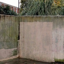
Trials have recently been carried out on the use of cement washes for graffiti-covered or repaired historic concrete. This may be a useful finishing technique for historic concrete for listed residential developments. Graffiti is first removed using chemicals (generally solvents and non-ionic surfactants) and the original concrete cleaned using high pressure hot or cold water jetting (Figure 12). This leaves a fairly patchy finish that is likely to revert back to its original mould-covered surface within a few years.
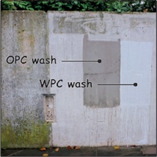
The trials involved applying a cement wash (50% water by volume) which fills up the pores in the weathered concrete and provides a smooth clean finish without removing the board-marked or other surface finishes (Figure 13). This is analogous to replacing the cement content in the weathered surface, a like-for-like replacement. The success of these trials allowed this particular finishing technique to be used in the autumn of 2014 on the concrete surfaces of a small park in a listed residential estate in north London.
PRACTICAL CONSIDERATIONS AND ALTERNATIVES
There are still some areas where like-forlike repairs are not suitable for historic concrete and modern lightweight repair mortar would be recommended. These include underside surfaces such as soffits, or where the original cover was minimal and the steel cannot be moved deeper into the concrete. Tests are currently under way to see if more adhesive traditional materials such as NHL5 (a strong natural hydraulic lime) could be used for these areas.
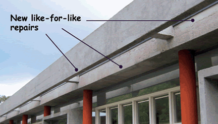
These and other traditional repair techniques more commonly associated with the work of stonemasons are increasingly being used for the conservation and repair of historic concrete, as at London’s National Theatre, Tecton’s buildings at Dudley Zoo, and the Alexandra Road Estate in Camden, London.
 |
 |
||
| Figure 14 (above) Tecton’s Safari Shop at Dudley Zoo following extensive conservation involving like-for-like repairs. Following extensive training, Dudley Zoo’s in-house maintenance team were able to carry out repair processes developed on site (above right). | |||
More extensive repairs may be required where reinforced concrete has been affected by chlorides, either because they were present in the original mix or because they had ingressed from a marine environment. In such cases cathodic protection may be required.
One of the 13 Tecton buildings at Dudley Zoo currently being repaired and conserved is the Safari Shop (Figure 14) which has been unused and neglected for decades. Here the original concrete was in a very poor condition with significant amounts of corrosion and delamination of the concrete cover. All repairs used like-for-like materials from the slab library. The exception was the soffits, where a modern lightweight repair mortar was used. On close examination the recent like-for-like repairs can be differentiated from the original concrete although the colour and texture match are close. However, in this case the original concrete building had always been coated, so a translucent silicate coating was specified which helped to blend in the repairs.
The concrete industry’s criticisms for specifying like-for-like repairs include:
- greater skill requirements of the operatives
- increased time to cut out and effect repairs
- the possibility of incipient anode corrosion (increased corrosion adjacent to the repairs).
At Dudley Zoo the skills issue was resolved through training the zoo’s in-house team to carry out the works. The time requirement has also been minimised by carrying out the various repair processes in batches.
The incipient anode problem has mainly been associated with chloride-infected concrete (marine environments and car park decks). This has not been identified on any of the traditional works carried out so far, although monitoring for this problem is currently being undertaken on one of the buildings at Dudley.
In conclusion, the authors are hoping to see broader use of concrete repairs closely matching the original structure, which will continue to weather in a similar manner, and which will improve the longevity of the buildings and enhance their unique character.
~~~
Recommended Reading
A Wiles, ‘St John and St Mary Magdalene, Goldthorpe: The Conservation of an Early Concrete Building’, Transactions (Association for Studies in the Conservation of Historic Buildings), vol 32, pp40-50, 2009
D Farrell and K Davies, ‘Repair and Conservation of Reinforced Concrete’, Historic Churches, Cathedral Communications Limited, Tisbury, 2005
English Heritage, Practical Building Conservation: Concrete, Ashgate, Farnham, 2012