4 6
T H E B U I L D I N G C O N S E R VAT I O N D I R E C T O R Y 2 0 1 4
T W E N T Y F I R S T E D I T I O N
1
PROFESSIONAL SERVICES
THERMAL IMAGING
INTHE INVESTIGATION OF SOLID
MASONRY STRUCTURES
MAUREEN YOUNG
T
HERMAL IMAGING
(also called
infrared thermography) is a type of
non-destructive investigation (NDI).
It allows the user to obtain data and analyse
an object without the need for a sample to be
removed and without damage to the object.
A wide range of non-destructive techniques
is available for use in building conservation.
Some are ‘active’ techniques where a signal
is sent out by the instrument. Information is
obtained by analysing changes in the returning
signal. Examples of this kind of NDI include:
• 3D laser scanning, which maps the
three-dimensional structure of objects.
• Microwave moisture analysis, where
the instrument projects a beam of
microwaves into a substrate and
quantifies sub-surface moisture.
Other NDI techniques are ‘passive’. They
do not emit a signal themselves, but are
dependent on detecting some emission by the
object.
• Heat flow sensors, used to determine
U-value, are a form of passive NDI. They
detect heat flow through a surface.
• Thermal imaging is, in the main, a
passive form of NDI. It detects infrared
light emitted by objects. However, some
specialist forms of thermal imaging do
involve active heating of surfaces, often to
observe rapid heating and cooling events.
WHAT IS THERMAL IMAGING?
Thermal imaging is a method for visualising
and quantifying temperature variations across
surfaces. Temperature differences as low as
0.1°C can be observed. It is a rapid method
allowing imaging of large surface areas. It is
non-destructive and non-contact, which can
be very important in some applications such as
electrical inspections.
Thermal imaging is a useful technique
for diagnosing the condition and behaviour of
many aspects of buildings, visually revealing
structural deficiencies. Applications include:
detection of moisture and water infiltration,
observing thermal bridges, voids, cracks or
delamination, locating areas of heat loss or
air leakage and assessing the performance
of insulation. Anything that results in a
temperature contrast on a surface can be
usefully imaged by thermography.
Thermal cameras look very like digital
photographic cameras but instead of using
visible light they detect infrared radiation
(IR), a form of light which is invisible to the
human eye as it occurs beyond the red end
of the visible light spectrum (0.4–0.76 μm).
IR cameras work with wavelengths between
2 and 14 μm, although no single camera covers
the entire range. Different types of IR camera
are appropriate for different applications.
Cameras which detect medium wave
IR (2–5 μm) are used in specialist laboratory,
medical and military applications. Cameras
for building thermography detect long wave
IR (8–14 μm). Although they are mainly used
to take single images, higher specification IR
cameras can also take images in time lapse
or video format. Specialist lenses allowing
telephoto and wide angle imaging are available.
Wide angle lenses can be particularly useful in
building thermography when working indoors
in small spaces or externally to capture wide
areas of facades in a single image.
The resolution of most thermal cameras is
not as high as that of photographic cameras.
Low-cost IR cameras have a resolution of about
60x60 pixels while some higher specification
cameras achieve 640x480 pixels. IR cameras
also vary in their thermal sensitivity (the
smallest difference in temperature they can
resolve). The more sensitive the detector, the
more detail will be visible in a thermal image,
especially when temperature differences are
relatively small.
Infrared radiation of the wavelengths
we are interested in (8–14 μm) does not
pass through glass. This means that the
camera cannot be used to see objects
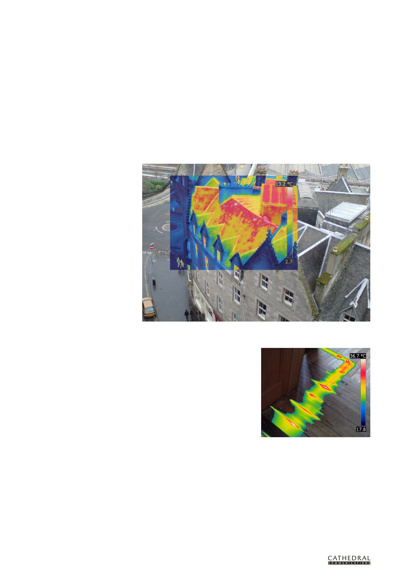
This thermal image inset within a digital image shows temperature variations across a roof using the ‘rainbow’
colour scheme. Each colour represents a temperature, shown in the scale on the right.
(All images: Historic Scotland).
It can be useful to combine parts of the temperature
range of a thermal image with a visual image. Here
the technique illustrates the path of a heating pipe
below floorboards.


