


 36 / 62

36
BCD SPECIAL REPORT ON
HISTORIC CHURCHES
24
TH ANNUAL EDITION
large diameter iron bars with large
pattress plates on the outside to anchor
them. The current practice is to use
bespoke stainless steel ties such as Cintec.
These are drilled through the full breadth
of each face of the tower from corner to
corner and grouted in place. The core
from the facing stone is then re-fixed,
leaving an almost invisible repair. The
positioning of these ties depends on the
configuration of the tower, but generally
they are positioned above the openings in
the walls at each level.
Some towers develop cracks in the
window reveals. These are more serious,
indicating that the wall thickness is
spreading due to the rubble fill in the
centre of the wall consolidating and
pushing the two masonry faces apart.
These cracks are quite common in flint
towers where the rounded flints in the
centre of the wall can move more easily
and wedge down into gaps between the
flints below, pushing the faces apart.
Spreading is likely to worsen with
continued bell ringing.
Through-thickness tying can be used
where there are stone or brick facings and
the cores can be grouted with a fluid lime
mortar grouting. Flint walls can be more
problematic due to the difficulty of coring
– drilling out the tie holes with a hollow
cylindrical bit – and the smaller size of
each flint. The Society for the Protection
of Ancient Buildings recommends cutting
pockets through the wall and building
in stainless steel mesh ties (see Further
Information), but this may be difficult to
achieve in practice.
NEW FOUNDATIONS
FOR BELL FRAMES
Occasionally, there is a requirement to
install a bell frame in a tower which has
not previously had full-swing bells. More
commonly, there is a requirement to
change the level of a bell frame. In both
cases it is first necessary to establish how
to install the bell frame while following
sound conservation principles.
In the mid-20th century, square
concrete rings were often cut into and
embedded in the internal faces of the
tower with either a concrete floor or
integral transverse beams supporting
the bell frames. This approach leads to
significant loss of original fabric and
would be difficult to reverse without
causing extensive damage to the original
masonry, particularly when breaking out
the embedded concrete.
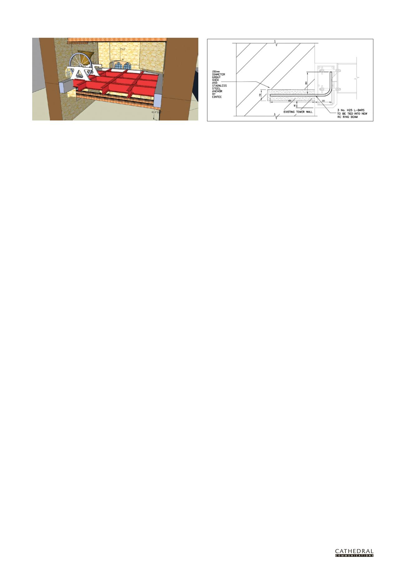
Nevertheless, the concrete ring
serves the fundamental function of
holding the four sides of the tower
together and spreading the forces from
the bell ringing more uniformly into
the walls. To retain these benefits while
minimising loss of fabric, one option is
to construct the reinforced concrete ring
beam adjacent to the inside face of the
tower and tie it to the walls by a series
of stainless steel anchor bars grouted
into 150mm diameter pockets cored into
the walls at regular intervals. If removal
were required, the ring beam could be
cut using vibrationless methods such as
diamond sawing and the anchors in the
wall could be cored out.
MONITORING FOLLOWING
CHANGES TO THE BELL FRAME
From the viewpoint of the bell ringers,
there is nothing to be gained by
monitoring after the changes have
taken place. However, by improving our
understanding of the behaviour of these
structures there is much to be learned.
The interaction between full swing
bells and bell towers is complex. The
forces are significant and all bell towers
move. The bell frames on which the bells
are mounted distort as the bells swing
and they are jerked when an adjacent bell
swings. Not only can these forces make
ringing difficult, but they can also be
highly destructive.
Monitoring can be used to identify
where movement is occurring and
may demonstrate that there is no
need for major changes if the frames
can be tightened up. Monitoring
can also show the movement shape
of the tower and the distortions of
the walls. However, monitoring will
not be able to determine how the
movement of the tower will change for
any given alterations to the frames.
With time, if sufficient pre- and post-
alteration monitoring is carried out, a
better understanding may develop. Harry
Windsor was undertaking this work
when he died. His work was voluntary,
my own is commercial. As a practising
structural engineer, I have found bell
ringers reluctant to fund work which
gives them no direct benefit and I have
not been called back to carry out post-
alteration monitoring. Until we have the
opportunity to carry out the ongoing
monitoring required, advising on the
impact of changing bell frames will
remain more an art than a science.
Further Information
AP Heywood,
Bell Towers and Bell
Hanging: An Appeal to Architects
,
Longmans & Co, London, 1914
D Lodge and A Wright,
Care and
Repair of Flint Walls
, SPAB Technical
Pamphlet 16, 2000 (see fig 8)
D Robinson and H Windsor,
A Practical
Analysis of the Interaction Between
Church Bells and Towers
, The Central
Council of Church Bell Ringers, 1994
R Smith and H Hunt, ‘Vibration of Bell
Towers Excited by Bell Ringing: a
new approach to analysis’, Cambridge
University Engineering Department,
Cambridge, 2008 (www2.eng.cam.
ac.uk/~hemh1/isma2008.pdf)
H Windsor,
Further Analysis of the
Interaction between Church Bells and
Towers
, The Central Council of Church
Bell Ringers, 2007
ANDREW DUTTON
MA(Cantab) CEng
FICE FIstructE (
adutton@hurstpm.co.uk)is a consulting engineer with Hurst Peirce
& Malcolm consulting structural engineers.
He is an accredited conservation engineer
under the CARE scheme and he specialises in
historic buildings, including church towers in
south east England.
This typical new bell frame foundation with a concrete ring beam inside the tower
walls was installed at All Saints, Fulham (see page 33).
A typical anchor tie into the wall