


 34 / 62

34
BCD SPECIAL REPORT ON
HISTORIC CHURCHES
24
TH ANNUAL EDITION
Timber bell frames were usually
mounted on timber foundation girders,
spanning across the tower but they
may have been replaced with steel
beams at some stage. The timber bell
frame foundation girders are usually
of substantial proportion but they will
still flex a little and they can also slip
in and out of the sockets in the walls.
Steel foundation beams are more flexible
and need to be substantially braced
to limit their flexing. In one church,
where a timber frame was mounted in
three parallel but unbraced steel beams,
the beams were found to be flexing
by over 6mm laterally during some
ringing sequences. The anchorages of
the steel beams in the walls can also be
problematic with hammering occurring.
The tower itself can be considered
as an elastic structure which will move
under the forces induced by bell ringing.
Ideally it will act as a single box which is
very stiff. However, there are normally
weaknesses in the walls of the tower in
the form of window and sound louvre
openings and it is not uncommon to
find vertical cracks running down the
centres of each wall from opening to
opening. These cracks effectively reduce
the stiffness from that of a box with a side
of ‘x’ to four angles with a side of half ‘x’,
which are therefore much less stiff. In
a sense, the action of the bell ringing is
trying to reduce the stiffness of the tower
to this lower state by increasing the size of
the cracks. The natural frequency of the
tower will change as the cracks develop.
Cracks can also develop in the
window reveals, indicating that the wall
thickness is spreading as the rubble fill
in the walls is shaken down. This is a
particular problem in flint towers.
While the bells are rung to a rhythmic
sequence, their different orientation
and the ringing changes mean that
the imposed forces do not rise and fall
smoothly in a simple sine wave, but result
in a series of jerks as each bell swings.
On occasions this can produce a sequence
of pulses which briefly match the natural
frequency of the tower.
MONITORING
With careful monitoring, it should
be possible to differentiate between
the movements of the bell frame, the
movements of the foundation beams
and the movement of the tower at
different levels. This requires measuring
movement in each of these three elements
simultaneously. From the three sets of
data it will be possible to discover what
portion of the total movement of the
top of the bell frame (and hence the
difficulty to ring) is due to slackness in
the bell frame, sway in the foundation
beams below, and sway in the tower as a
whole. The bell ringers can then assess the
benefits to be gained from various levels
of improvement.
It could easily be the case that a
50 per cent reduction in the movement
at the bell pivots can be achieved by
improvements to a timber bell frame,
whereas the more expensive option of
installing new foundation beams might
only give a 10 per cent improvement.
Similarly, the even more expensive option
of lowering the bell frame in the tower
to reduce sway itself may give only a
very small improvement and, for reasons
which will be discussed later, could even
result in greater movement.
Monitoring can take many forms
depending on what is being sought.
A finger placed across a crack running up
the centre of the wall during ringing will
be sensitive enough to feel whether the
crack is ‘working’ (opening and closing).
To determine the benefit of tightening up
a timber frame or replacing it with a metal
frame, it is possible to install temporary
wedging and blocking between the
frames and the walls so they cannot move
differentially to the tower. This is only a
temporary expedient, however, because
potential hammering as the wedges
loosen can damage the masonry.
Ideally, accurate electronic
measurement of all elements
simultaneously will yield the most
information. Electronic measurement of
bell frame movement was developed by
the late Harry Windsor of the Central
Council of Church Bell Ringers when
it became apparent that a lowered
bell frame had resulted in increased
movement in one church tower. Windsor
produced a publication on his method
of monitoring and his assessment of why
the movement might have increased,
based on the harmonics of the bell ringing
matching the natural frequency of the
tower. He was about to publish a revision
to his booklet when he died in 2007
(see Further Information, Windsor).
Windsor’s method of monitoring
employed accelerometers mounted
on the bell frames and tower with
a data logger. The accelerometer
information then had to be transferred to
spreadsheets for the actual displacement
to be calculated by the mathematical
process of double integration, a slow and
tedious process.
At this time I was developing my own
electronic system which automatically
calculated displacements from the
accelerations and simultaneously carried
out the data integration as a continuous
process, allowing instant plots of the
movement. Three accelerometers, each
able to measure the acceleration in the
x and y directions simultaneously, could
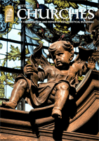
This plot shows the movement in the north and south walls of the bell chamber
when all bells oriented east-west (the Y axis) are rung simultaneously, producing
a large pulse. The effect on the tower is captured by accelerometers attached to
the masonry of the north and south walls of the bell chamber. The pulse leads to a
jerk on the east-west axis (yellow and green lines) which is much longer than the
natural frequency of the tower which is just over 2Hz.
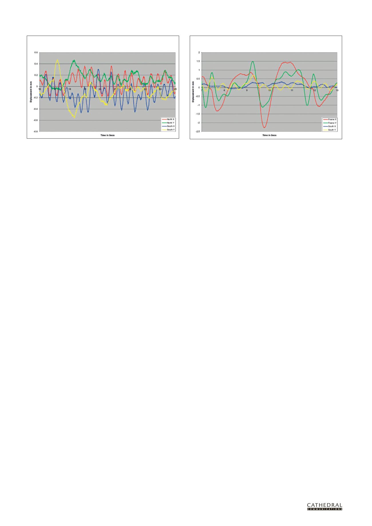
A comparison between the movement of the frame on the north-south (X) axis
in red, and the much smaller movement of the south wall (blue) on the same
axis. This shows the considerable benefit which can be achieved by stiffening up
the frame.
PLOT A: Bells ‘firing’ east-west simultaneously, with accelerometers on
north and south walls of bell chamber
PLOT B: Bells ‘firing’ north-south simultaneously, with accelerometers on
bell frame and on south wall of bell chamber