


 35 / 62

BCD SPECIAL REPORT ON
HISTORIC CHURCHES
24
TH ANNUAL EDITION
35
be mounted at key locations. Typical
locations are on the bell frame at pivot
level, on the foundation beams and on
the tower walls in the bell chamber.
Another combination may be to locate
the accelerometers at different positions
up the tower to measure the tower shape
as it moves. This, in conjunction with
measuring the natural frequency of the
tower, will help to predict the benefits
of changing the level of the bell frame.
Plots A–C (above) show the movement
for various combinations of excitation at
different locations within the same tower.
When monitoring the movement,
there are a number of methods of
excitation. To measure the natural
frequency of the tower, a single pulse
input while measuring the decay
frequency would be optimum. It is
not possible to achieve that with a full
circle swing of a bell due to the complex
combination of forces which are applied
as the bell swings. A better method is
to have a heavy sandbag swinging on a
rope and impacting on a wall. However,
in reality, even when ringing a peal, it is
possible to pick out the natural frequency
from the plots (Plot D).
Determining the maximum potential
movement of the tower can be difficult
due to the wide range of peal sequences.
I have used a combination of the bob
minor peal (when bells are rung in
sequence) and ‘firing’ (when all the bells
are rung simultaneously) in one of the
orthogonal directions. Firing will produce
a large jerk (see Plots A–C).
Where there are cracks of specific
concern, it is possible to measure the
movement in each side of the crack
simultaneously, with the difference
between the two plotlines representing
the movement at the crack.
There is a limit to the accuracy of
the movement recorded. The electronic
integration method introduces background
‘noise’ in the signal. As a result, movements
of less than about 0.2mm will be lost in the
background noise.
One clear lesson of the monitoring is
that human perception is very sensitive
and actual movement is usually much less
than people expect.
BELL FRAME ALTERATIONS
Stiffening up the bell frame or foundation
beams to reduce movement of the tower
can have unpredictable effects. The
slackness in the system means that the
energy transfer from the bells to the tower
is delayed, with energy temporarily stored
in the frames and beams as they flex, and
then released at slightly different times.
This can change the frequency of the
forces imposed on the tower and it can
also increase them.
Imagine placing a football against
a wall and kicking it onto the wall. The
impact on the foot, and hence the wall
will be tolerable. Now replace the ball
with a hollow metal ball of the same
mass and kick. Broken toes could be the
result, indicating a much higher impact
force. The energy absorption of the
frames and foundation beams is similar.
It is possible that stiffening of the frames
and foundation beams could increase
the movement of the tower, either due
to the sharper impact pulse or because
the modified input frequency is nearer
to the natural frequency of the tower.
Unfortunately, monitoring of the tower
will not help with this dilemma.
Changing the level of the bell frame
can also have unpredictable effects if
it means that the force is applied at a
position nearer to the point of maximum
movement of the tower. Some towers
will sway as a simple cantilever from
the ground. Others, possibly with stone
spires with a higher centre of mass, may
develop a ‘standing node’ approximately
two thirds of the height, about which the
structure oscillates. If the force is applied
near the point one third of the height,
excitation can occur. Hence the need to
monitor the shape of the displacement up
the tower. Harry Windsor and others have
attempted to analyse what happens but it
seems to me that too many changes take
place when a bell frame is altered to allow
isolation of specific parameters.
Changing the configuration of the
bells in the frame can also change the
forces on the tower. One of the reasons
bell ringers want to have their bell frames
modified is to improve the arrangement
of the hanging bell ropes. Ideally, they
should form a circle so that each ringer
can see all the other ringers. This often
means changing the direction of swing
of some of the heavier bells. The tenor
might have been swinging east-west for
200 years and will now swing north-south
and be close to the west wall of the tower.
The north-south forces in the west wall
could increase significantly.
TOWER WEAKNESSES, CRACKS
AND REMEDIAL MEASURES
Generally, where vertical cracks have
developed in the centre of each wall of a
tower, these do not get significantly worse
after formation. However, if they do ‘work’
during ringing, tiny particles of debris
will work their way down the cracks,
slowly enlarging them. Cracks can also be
worsened if changes made to a bell frame
alter the forces induced in the tower walls.
For this reason, when it is proposed to
alter a bell frame in a way that will change
the forces induced in the tower, it is
recommended that the cracks are tied.
Historically, cracks were tied with
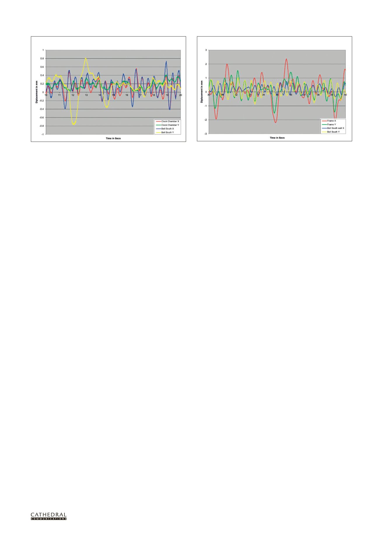
This plot shows the movement of the south wall at bell chamber level and the
clock chamber 4m below. It can be noted that the impulse momentarily distorts
the wall of the bell chamber in the east-west axis (yellow) while the wall below
(green) moves much more closely with the natural frequency of the tower.
With a peal (with bells swung in both axes), the frames move much more than
the wall in both X (red) and Y (green) axes. The yellow and blue plots give a
clear indication of the natural frequency of the tower in each direction.
PLOT C: Bells ‘firing’ east-west simultaneously, with accelerometers on
south wall of bell chamber and south wall of clock chamber
PLOT D: Full peal, with accelerometers on bell frame and
south wall of bell chamber